

Convenient in-place method for large refrigerating unit
A refrigeration unit and convenient technology, applied in household refrigeration devices, lighting and heating equipment, household appliances, etc., can solve the problems of large size, labor consumption, time, and weight of refrigeration units, reduce the possibility of damage to equipment, and be flexible in use. , The effect of improving installation efficiency
- Summary
- Abstract
- Description
- Claims
- Application Information
AI Technical Summary
Problems solved by technology
Method used
Image

Examples
Embodiment Construction
[0032] The following will clearly and completely describe the technical solutions in the embodiments of the present invention with reference to the accompanying drawings in the embodiments of the present invention. Obviously, the described embodiments are only some, not all, embodiments of the present invention. Based on the embodiments of the present invention, all other embodiments obtained by persons of ordinary skill in the art without making creative efforts belong to the protection scope of the present invention.
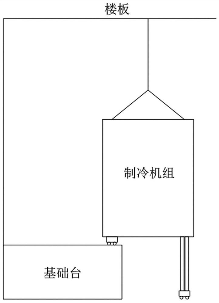
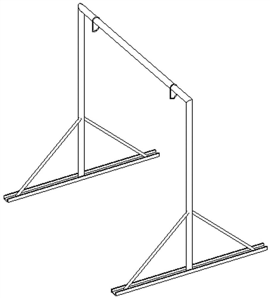
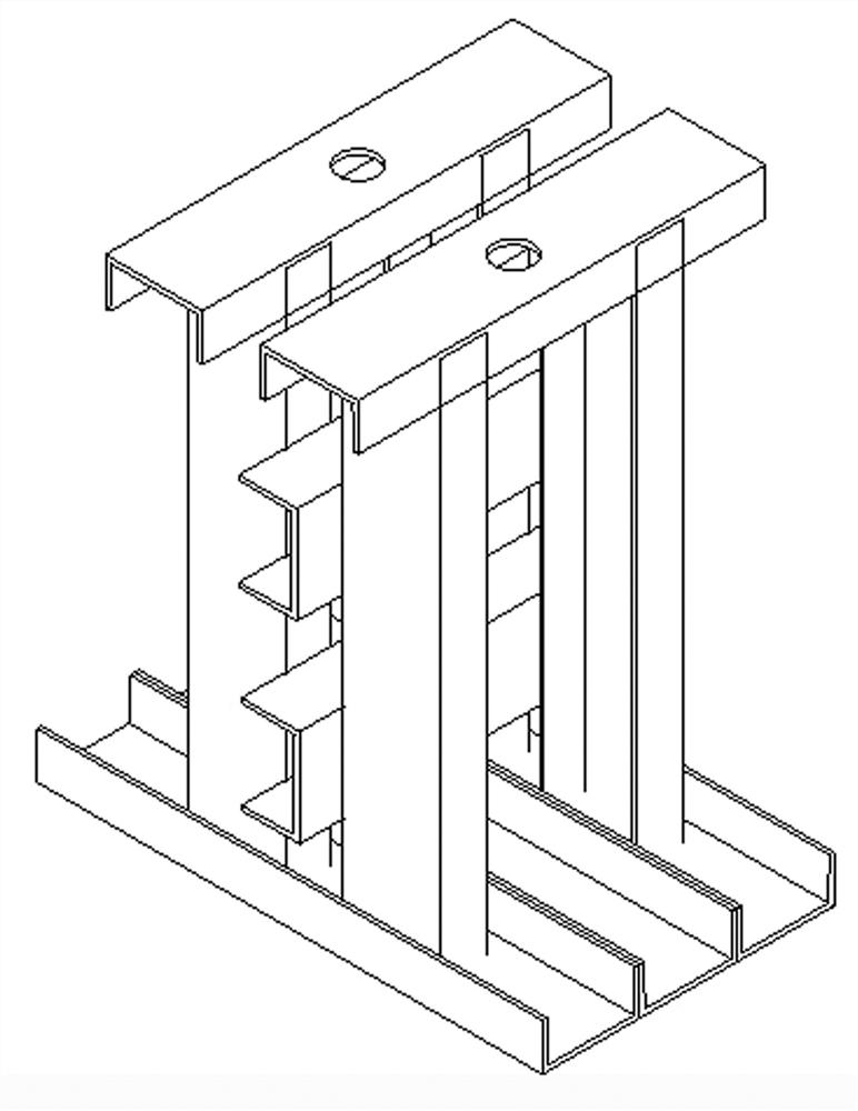
[0033] see Figure 1 to Figure 3 , the present invention provides a convenient positioning method for a large-scale refrigeration unit, which does not change the original handling method, reduces the number of times the floor is punched and fixed at different positions during two lifts, only needs to be removed once, and at the same time reduces Labor and time costs are reduced, and installation efficiency is also improved. Include the following steps:
[00...
PUM
 Abstract
Description
Claims
Application Information