MEMS inertia switch with adjustable threshold value

An inertial switch and threshold technology, applied in the field of MEMS inertial switches, can solve problems such as the inability to quantitatively analyze the value of acceleration, and achieve the effects of increasing complexity, changing the outer contour, and adding structures and methods

Active Publication Date: 2021-01-29
SHANGHAI JIAO TONG UNIV
View PDF13 Cites 4 Cited by
  • Summary
  • Abstract
  • Description
  • Claims
  • Application Information

AI Technical Summary

Problems solved by technology

[0006] The object of the present invention is to provide a MEMS inertial switch with adjustable threshold, t...

Method used


Image

  • MEMS inertia switch with adjustable threshold value
  • MEMS inertia switch with adjustable threshold value
  • MEMS inertia switch with adjustable threshold value

Examples


Embodiment Construction

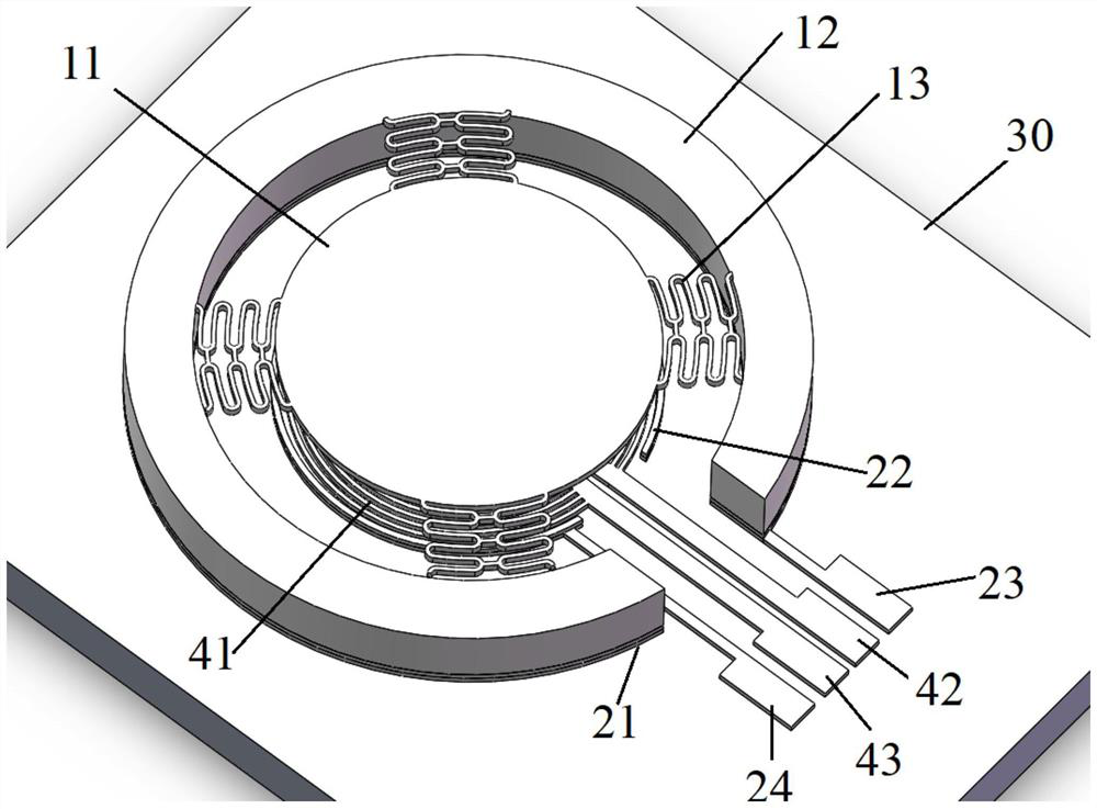
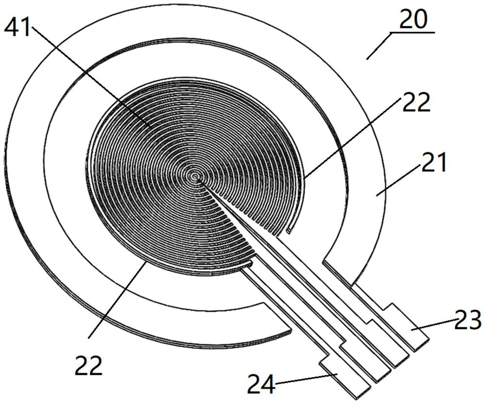
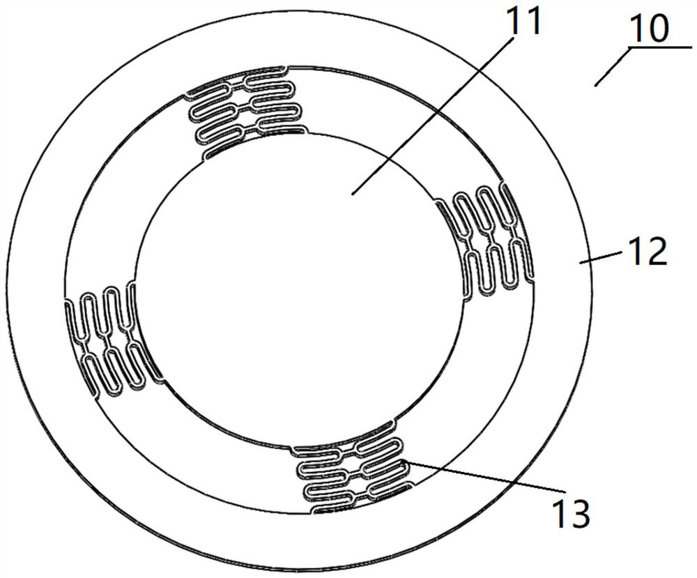
[0048] The threshold-adjustable MEMS inertial switch proposed by the present invention will be further described in detail below in conjunction with the accompanying drawings and specific embodiments. Advantages and features of the present invention will be apparent from the following description and claims. It should be noted that all the drawings are in a very simplified form and use imprecise scales, and are only used to facilitate and clearly assist the purpose of illustrating the embodiments of the present invention.

[0049] In addition, unless otherwise stated, features in different embodiments of the present invention can be combined with each other. For example, a feature in the second embodiment may be used to replace a corresponding or functionally identical or similar feature in the first embodiment, and the resulting embodiment also falls within the scope of disclosure or description of the present application.

[0050] The core idea of ​​the present invention is t...


PUM

PropertyMeasurementUnit
Radiusaaaaaaaaaa
Radiusaaaaaaaaaa
Widthaaaaaaaaaa

Abstract

The invention provides an MEMS inertial switch with an adjustable threshold value, wherein the switch comprises an induction upper electrode, an induction lower electrode and an electromagnetic attraction device; the induction upper electrode is configured to move towards an induction lower electrode under the action of inertia, and forms a pulse induction signal when the induction upper electrodeis in contact with the induction lower electrode; the induction lower electrode is configured to be fixedly arranged with a shell, and when the induction lower electrode is in contact with the induction upper electrode, a pulse induction signal is formed; and the electromagnetic attraction device is configured to generate a magnetic field after current is introduced, the magnetic field generatesacting force towards the induction lower electrode on the induction upper electrode, and the intensity and direction of the magnetic field change along with the change of the introduced current.

Description

technical field [0001] The invention relates to the technical field of inertial switches, in particular to a MEMS inertial switch with adjustable threshold. Background technique [0002] In the fields of aerospace, automobile industry, inertial navigation, ammunition safety and control system, automobile detection, torpedo control and other fields, various new technologies are constantly emerging, and all kinds of detection and control equipment are moving towards the direction of miniaturization, low energy consumption and intelligence develop. In this situation, it is required that the used sensing elements and actuating elements not only meet the requirements of miniaturization, but also provide reliable stability. Micro-inertial components based on MEMS (Micro-Electro-Mechanical System, Micro-Electro-Mechanical System) technology came into being based on the above reasons, and give full play to their advantages of being small, flexible and intelligent. [0003] Micro-E...

Claims


Application Information

Patent Timeline
IPC IPC(8): G01P15/08G01P15/105G01P15/135H03K17/90
CPCG01P15/08G01P15/0802G01P15/105G01P15/135G01P2015/0862H03K17/90
Inventor 杨卓青张鹏磊任超李亚辉丁桂甫张浩东连江凯
Owner SHANGHAI JIAO TONG UNIV
Why Eureka
Try Eureka