Automobile exhaust system

An automobile exhaust system and exhaust pipe technology, which is applied to exhaust devices, mufflers, internal combustion piston engines, etc., can solve the problems of pumping loss and limited effect in the exhaust system, and achieve exhaust gas circulation. Smooth, cost-effective results

Inactive Publication Date: 2018-06-12
CHERY AUTOMOBILE CO LTD
View PDF5 Cites 0 Cited by
  • Summary
  • Abstract
  • Description
  • Claims
  • Application Information

AI Technical Summary

Problems solved by technology

However, the effects obtained by the above methods are often very limited, and cannot well solve the problem of pump air loss caused by the back pressure of the exhaust system.

Method used


Image

  • Automobile exhaust system

Examples


Embodiment Construction

[0023] The specific implementation manner of the present invention will be described in further detail below by describing the embodiments with reference to the accompanying drawings.

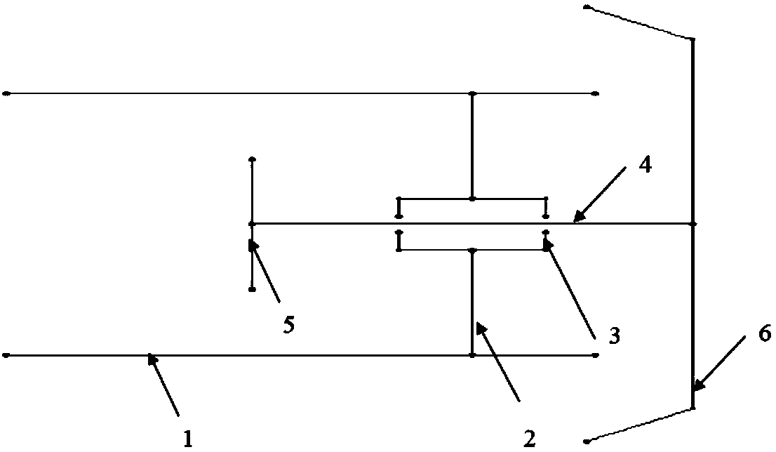
[0024] Such as figure 1 As shown, the automobile exhaust system includes an exhaust pipe and an exhaust decompression structure. The exhaust decompression structure is used to reduce the internal pressure of the exhaust pipe, so that the exhaust gas in the exhaust system can flow more smoothly.

[0025] The exhaust decompression structure is installed at the outlet of the exhaust pipe in the automobile exhaust system. It can be installed on the exhaust tailpipe through the connection of clamps or bolts, or it can be integrated by installation or welding during the development process. at the end of the exhaust pipe.

[0026] The exhaust depressurization structure includes a hollow shell 1, one end of the hollow shell 1 is connected to the outlet of the exhaust pipe, and the other end of the ho...


PUM


Abstract

The invention discloses an automobile exhaust system. The system comprises an exhaust pipe. An outlet of the exhaust pipe is connected with an exhaust depressurization structure used for reducing pressure in the exhaust pipe. The automobile exhaust system is additionally arranged at the tail of an automobile exhaust pipe, so that pressure at the outlet end of an exhaust system during working of anautomobile engine is effectively reduced, the inner pressure can be made lower than the atmospheric pressure under normal working conditions, certain negative pressure can also be formed under certain special automobile travelling working conditions, accordingly, circulation of exhaust gas in the exhaust system can be made smoother, meanwhile, a suction effect can be achieved, thus, work lost dueto gas pumping of the engine can be reduced, and therefore, the economical efficiency of the engine is effectively improved.

Description

technical field [0001] The invention relates to the technical field of automobile exhaust, in particular to an automobile exhaust system. Background technique [0002] With the continuous increase of car ownership in China and even the world, the air pollution is becoming more and more serious, and accompanied by the continuous reduction of oil reserves. Driven by these two conditions, the fuel consumption of automobile internal combustion engines is becoming more and more strict. The industry is always exploring various technical means to reduce fuel consumption and improve the economic performance of the engine, and the maximum energy consumption of the engine’s pumping loss can reach 10%, so a technical means is needed to solve the problem caused by the exhaust gas. resulting in energy loss. [0003] The pump air loss is mainly caused by two parts in the structural design. The first is the design of the exhaust valve. At present, the industry adopts the method of large e...

Claims


Application Information

Patent Timeline
IPC IPC(8): F01N13/08F01N5/04
CPCF01N5/04F01N13/08Y02T10/12
Inventor 李艳光黄波
Owner CHERY AUTOMOBILE CO LTD
Why Eureka
Try Eureka