A phase delay device, its preparation method, and display device

A technology of phase delay and delay amount, applied in the field of display equipment, phase delay device and preparation method thereof, can solve the problems of poor side viewing angle performance of display screen and the like

Active Publication Date: 2021-03-02
BEIJING RAYBOCH TECH CO LTD
View PDF6 Cites 0 Cited by
  • Summary
  • Abstract
  • Description
  • Claims
  • Application Information

AI Technical Summary

Problems solved by technology

[0004] The purpose of the embodiment of this specification is to provide a phase delay device, its preparation method, and display device, so as to solve the problem in the prior art that the display screen has poor side viewing angle performance under wide-band

Method used


Image

  • A phase delay device, its preparation method, and display device
  • A phase delay device, its preparation method, and display device
  • A phase delay device, its preparation method, and display device

Examples


Embodiment 1

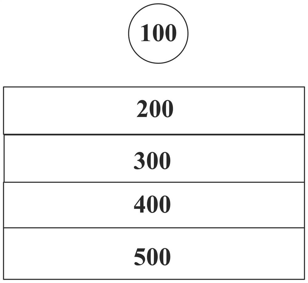
[0041] figure 1 Schematic diagram of the structure of the phase delay device provided for the embodiment of this specification Figure 1 , the phase retardation device includes: a first polarizing layer 200, a first phase retardation layer 300, a second phase retardation layer 400 and a second polarizing layer 500, wherein:

[0042] The first polarizing layer 200 may be located at one side of the light source 100 for converting received light into linearly polarized light. The light source 100 may be any light source 100 capable of emitting natural light, and the first polarizing layer 200 may include any device capable of converting the natural light emitted by the light source 100 into linearly polarized light, such as a linear polarizer, a wire grid polarizer, and the like.

[0043] The first phase retardation layer 300 may be located on a side of the first polarizing layer 200 away from the light source 100 for converting linearly polarized light into elliptically polarized...

Embodiment 2

[0058] An embodiment of the present invention provides yet another phase delay device. The phase delay device includes all the functional units of the phase delay device of the first embodiment above, and on the basis of it, it is improved, and the improvements are as follows:

[0059] The refractive index of the first phase retardation layer 300 can satisfy in, is the refractive index in the retarded phase axis direction of the first phase retardation layer 300, is the refractive index in the advanced phase axis direction of the first phase retardation layer 300, is the refractive index in the thickness direction of the first phase retardation layer 300,

[0060] The refractive index of the second phase retardation layer 400 can satisfy in, is the refractive index in the direction of the retarded phase axis of the second phase retardation layer 400, is the refractive index in the advanced phase axis direction of the second phase retardation layer 400, is the re...

Embodiment 3

[0082] An embodiment of the present invention provides a display device, which may include at least one phase delay device as described in Embodiment 1 and Embodiment 2 above, wherein:

[0083] The first polarizing layer 200 may be located at one side of the light source 100 for converting received light into linearly polarized light.

[0084] Such as Figure 7 As shown, between the first polarizing layer 200 and the first phase retardation layer 300, a liquid crystal display panel may be arranged, and the liquid crystal display panel may be an in-plane switching (In-Plane Switching, IPS) liquid crystal display panel, fringe field switching technology ( Fringe Field Switching, FFS) liquid crystal display panel, etc.

[0085] The first phase retardation layer 300 may be used to convert linearly polarized light into elliptically polarized light.

[0086] The second phase retardation layer 400 may be located on a side of the first phase retardation layer 300 away from the first...


PUM


Abstract

The embodiment of this specification discloses a phase retardation device, its preparation method, and a display device. The phase retardation device includes: a first polarizing layer, a first phase retardation layer, a second phase retardation layer, and a second polarizing layer; The first polarizing layer is located on one side of the light source, and is used to convert the received light into linearly polarized light; the first phase retardation layer is located on the side of the first polarizing layer away from the light source, and is used to convert the received light into linearly polarized light. converting linearly polarized light into elliptically polarized light; the second phase retardation layer is located on a side of the first phase retardation layer away from the first polarizing layer, and is used to convert the elliptically polarized light into linearly polarized light; The second polarizing layer is located on a side of the second phase retardation layer away from the first phase retardation layer, and is used to absorb the linearly polarized light; the first phase retardation layer and the second phase retardation layer Birefringence does not decrease with increasing wavelength of visible light.

Description

technical field [0001] This description relates to the field of display technology, in particular to a phase delay device, a manufacturing method thereof, and a display device. Background technique [0002] With the continuous popularization of terminal equipment such as mobile phones, tablet computers, and vehicle displays, light-weight and small Liquid Crystal Displays (LCD) have emerged. Among them, IPS and FFS types of LCD displays have better viewing angles. occupied a larger market. [0003] At present, in order to improve the performance of the side viewing angle, IPS and FFS type LCD displays can add a compensation film to the polarizer, such as a compensation film formed by superimposing +A Plate and +C Plate of positively distributed liquid crystals. However, due to the poor characteristics of positively distributed liquid crystals after film formation, this kind of compensation film structure cannot avoid the problem of light leakage in the dark state caused by t...

Claims


Application Information

Patent Timeline
Patent Type & Authority Patents(China)
IPC IPC(8): G02F1/13363G02F1/1335G02F1/1337
CPCG02F1/13363G02F1/133528G02F1/133788
Inventor 赵文卿
Owner BEIJING RAYBOCH TECH CO LTD
Why Eureka
Try Eureka