Annular inductor automatic winding equipment

A toroidal inductor and automatic winding technology, applied in the field of inductance, can solve the problems of difficult to pass detection, low winding efficiency, difficult to fit tightly, etc., to achieve the effect of fast and convenient insertion and fixation, and improve efficiency

Active Publication Date: 2021-01-29
通友智能装备(江苏)有限公司
View PDF7 Cites 1 Cited by
  • Summary
  • Abstract
  • Description
  • Claims
  • Application Information

AI Technical Summary

Problems solved by technology

[0004] Aiming at the deficiencies of the prior art, the present invention provides an automatic winding device for a ring inductor, which has the ability to quickly wind the wire on the inductance coil, improves the winding efficiency, and the wire wound on the inductance coil can be tightly attached , avoiding the large wire spacing caused by the inductance coil rotating too fast, so that the wires on the inductance coil can be protected, avoiding the advantages of being pressed and dented when the wires on the inductance coil increase, and solving the problem of manual winding, winding The effect is not ideal, and the winding efficiency is low. In the actual winding process, the wires manually wound on the inductance coil have a large distance between the wires and it is difficult to fit tightly. It is difficult to pass the inspection and pass the test. Due to manual When winding the wire, it is necessary to use a winding rod to wind the wire, which is easy to cause the problem of pressing and sag on the wire

Method used


Image

  • Annular inductor automatic winding equipment
  • Annular inductor automatic winding equipment
  • Annular inductor automatic winding equipment

Examples


Embodiment Construction

[0029] The following will clearly and completely describe the technical solutions in the embodiments of the present invention with reference to the accompanying drawings in the embodiments of the present invention. Obviously, the described embodiments are only some, not all, embodiments of the present invention. Based on the embodiments of the present invention, all other embodiments obtained by persons of ordinary skill in the art without making creative efforts belong to the protection scope of the present invention.

[0030] As introduced in the background, there are deficiencies in the prior art. In order to solve the above technical problems, the present application proposes an automatic winding device for a ring inductor.

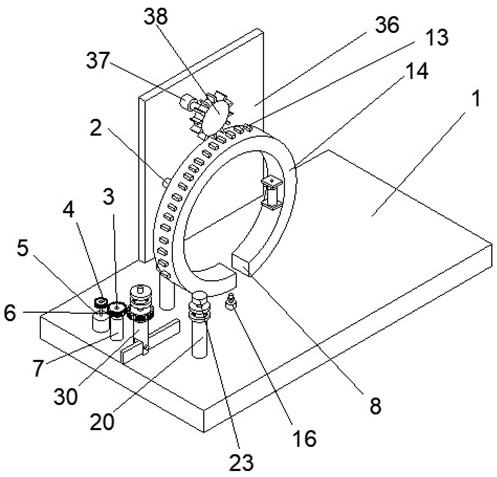
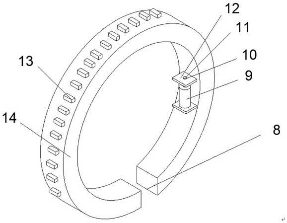
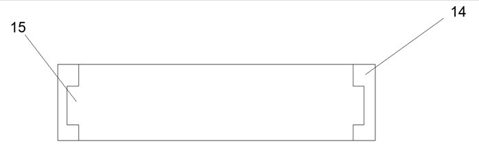
[0031] In a typical implementation of the present application, such as Figure 1-Figure 9 As shown, a ring-shaped inductor automatic winding device includes a base plate 1, the base plate 1 is a rectangular plate, and the left end of the top surface o...


PUM


Abstract

The invention relates to the technical field of inductors, and discloses annular inductor automatic winding equipment, which comprises a bottom plate, and an inductor rotating power structure is arranged at the left end of the top face of the bottom plate and used for providing power for rotation of an inductor; an inductor rotating power transmission structure is arranged at the left end of the top face of the bottom plate and used for transmitting power; a stabilizing plate is fixedly installed in the center of one side of the top face of the bottom plate, and an inductor winding power structure is arranged in the center of the top of the side wall, facing the bottom plate, of the stabilizing plate and used for providing power for inductor winding; side columns are fixedly installed at the left end and the right end of the side, facing the bottom plate, of the stabilizing plate correspondingly, and inductor winding supporting structures are arranged at the front ends of the side columns and used for supporting the inductor winding structures; and a limiting strip is fixedly installed in the center of the left end of the top face of the bottom plate, and inductor rotating supporting structures are arranged on the limiting strip and the top face of the bottom plate and used for supporting and rotating the inductor.

Description

technical field [0001] The invention relates to the technical field of inductance, in particular to an automatic winding device for a ring inductor. Background technique [0002] An inductor is a circuit element that resists a change in current by generating an electromotive force due to a change in current passing through it. The most primitive inductor is the iron core coil where Faraday discovered the phenomenon of electromagnetic induction in England. The structure of an inductor is similar to that of a transformer, but there is only one winding, which is generally composed of a skeleton, a winding, a shield, a packaging material, a magnetic core or an iron core, etc. If the inductor is in a state where there is no current flowing, it will try to block the current flow through it when the circuit is on; if the inductor is in a state where current is passing, it will try to maintain the current when the circuit is off. Inductance is the ratio of the magnetic flux of the...

Claims


Application Information

Patent Timeline
IPC IPC(8): H01F41/06
CPCH01F41/06
Inventor 高彦华周晟
Owner 通友智能装备(江苏)有限公司
Why Eureka
Try Eureka