Virus storage tank virus-killing and inactivating device for virus protection
A technology for storage tanks and viruses, which is applied in the field of anti-virus and inactivation devices for virus storage tanks, can solve the problems of high labor intensity, low labor intensity, and low efficiency, and achieve the effect of comprehensive disinfection and improved work efficiency
- Summary
- Abstract
- Description
- Claims
- Application Information
AI Technical Summary
Problems solved by technology
Method used
Image
Examples
Embodiment 1
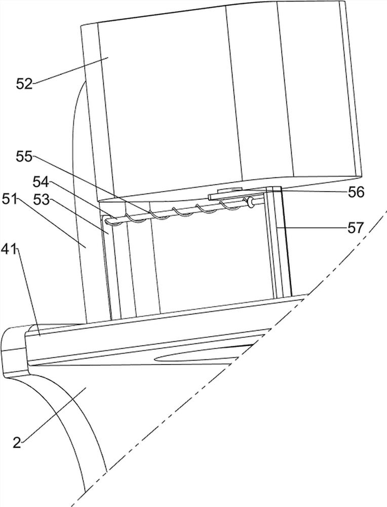
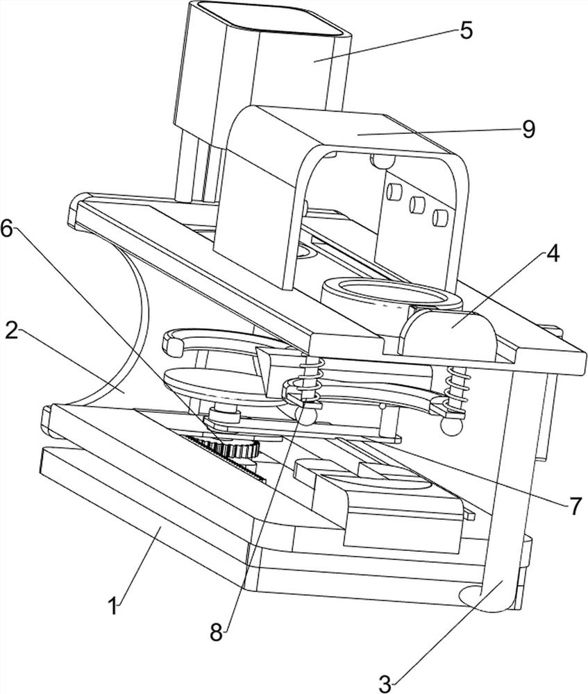
[0066]A virus storage tank antivirus and inactivation device for virus protection, such as figure 1 and figure 2 As shown, it includes a base 1, a support base 2, a first support column 3, a pushing mechanism 4 and an automatic feeding mechanism 5. The base 1 is provided with a support base 2 on the rear side, and the base 1 is provided with a first support on the right side of the front side. Column 3, a push mechanism 4 is connected between the top of the first support column 3 and the support base 2, the top of the support base 2 is provided with an automatic feeding mechanism 5, and the automatic feeding mechanism 5 cooperates with the push mechanism 4.
[0067] Manual manual operation has high labor intensity, low efficiency and incomplete anti-virus. This equipment can automatically kill and inactivate virus storage tanks, with low labor intensity, high efficiency and comprehensive anti-virus. virus storage tank, and pour disinfectant into the automatic feeding mechani...
Embodiment 2
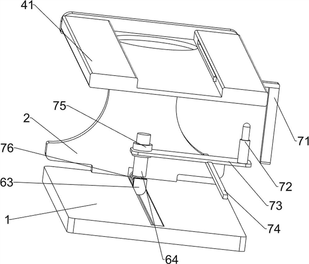
[0069] On the basis of Example 1, as figure 2 , image 3 and Figure 5 As shown, the push mechanism 4 includes a first groove block 41, a first fixing block 42, a cylinder 43, a push ring 44 and a buffer ring sleeve 45, and a first groove is connected between the top of the first support column 3 and the support base 2 The groove block 41 is provided with a first fixing block 42 in the middle of the front side of the top of the first groove block 41 , a cylinder 43 is provided on the rear side of the first fixing block 42 , and a push ring 44 is provided on the back side of the cylinder 43 . The groove blocks 41 are slidably connected, and a buffer ring sleeve 45 is provided on the inner side of the rear of the first groove block 41 .
[0070] People put the unsterilized virus storage tank in the push ring 44, and then open the air cylinder 43. The operation of the air cylinder 43 will cause the push ring 44 to slide back and forth in the first groove block 41 repeatedly. W...
Embodiment 3
[0074] On the basis of Example 2, as figure 1 , Figure 4 , Figure 5 , Image 6 and Figure 7 As shown, a rotating mechanism 6 is also included. The rotating mechanism 6 includes a second groove block 61, a push block 62, a push frame 63, a rotating block 64, a gear 65 and a rack 66. The front side of the top of the base 1 and the support base 2 A second groove block 61 is connected to the lower part of the front side, a push frame 63 is slidably provided inside the second groove block 61, the push frame 63 is slidably connected to the base 1, and a push block 62 is provided in the middle of the top rear side of the push frame 63, A rotating block 64 is rotatably provided in the middle of the front side of the top of the push frame 63. The rotating block 64 passes through the push frame 63. The rack 66 meshes with the gear 65 .
[0075] The virus storage tank that has been disinfected will fall to the top of the rotating block 64 through the buffer ring sleeve 45 due to ...
PUM
 Abstract
Description
Claims
Application Information
 - R&D
- Intellectual Property
- Life Sciences
- Materials
- Tech Scout
- Unparalleled Data Quality
- Higher Quality Content
- 60% Fewer Hallucinations
Browse by: Latest US Patents, China's latest patents, Technical Efficacy Thesaurus, Application Domain, Technology Topic, Popular Technical Reports.
© 2025 PatSnap. All rights reserved.Legal|Privacy policy|Modern Slavery Act Transparency Statement|Sitemap|About US| Contact US: help@patsnap.com


