Eureka AIR delivers breakthrough ideas for toughest innovation challenges, trusted by R&D personnel around the world.

Clamp for clamping engine cylinder block

A cylinder block and engine technology, applied in the direction of manufacturing tools, workpiece clamping devices, etc., can solve problems such as troublesome, unreliable fixation, and irregular shape

Inactive Publication Date: 2021-02-02
JIANGMEN CHAOYANG PRECISION MFG
View PDF6 Cites 2 Cited by
  • Summary
  • Abstract
  • Description
  • Claims
  • Application Information

AI Technical Summary

Problems solved by technology

[0002] With the continuous development of my country's economy, the demand for engines is increasing. During the production process of the engine cylinder block, it is necessary to process the shape, size and surface quality of the cylinder block. Generally, workpieces with regular shapes can be processed by using a vise. Fixed, but the shape of the engine cylinder block is various, and the shape is irregular. If it is fixed with a vise, it will lead to unreliable fixation and easy to loosen. Therefore, people need to make a specific clamping structure for various shapes of engine cylinder blocks. fixture, very troublesome

Method used


Image

  • Clamp for clamping engine cylinder block
  • Clamp for clamping engine cylinder block

Examples


Embodiment Construction

[0017] Embodiments of the present invention are described in detail below, examples of which are shown in the drawings, wherein the same or similar reference numerals designate the same or similar elements or elements having the same or similar functions throughout. The embodiments described below by referring to the figures are exemplary only for explaining the present invention and should not be construed as limiting the present invention.

[0018] In the description of the present invention, it should be understood that when it comes to orientation descriptions, for example, the orientation or positional relationship indicated by up, down, etc. is based on the orientation or positional relationship shown in the drawings, which is only for the convenience of describing the present invention and simplifying the description , rather than indicating or implying that the device or element referred to must have a particular orientation, be constructed and operate in a particular o...


PUM


Abstract

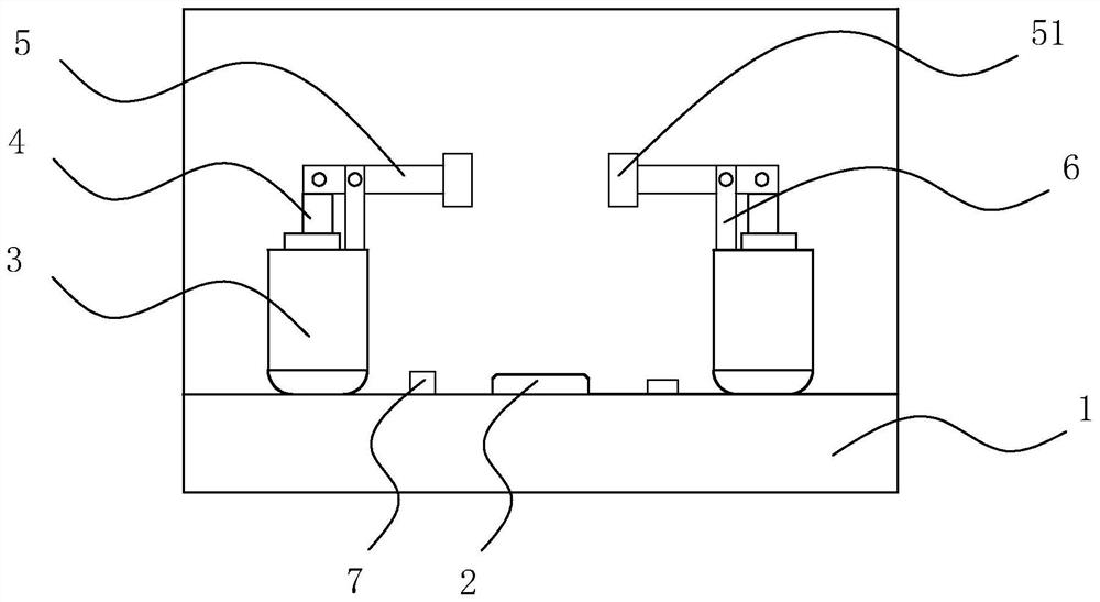
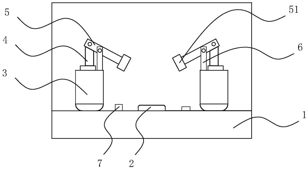
The invention discloses a clamp for clamping an engine cylinder block. The clamp comprises a base, wherein a positioning buffer block is arranged on the base; piston cylinders are arranged at the twosides of the positioning buffer block respectively; piston rods are arranged on the piston cylinders; pressing rods are hinged to the piston rods; supporting rods are fixedly arranged on the piston cylinders; and the ends of the supporting rods are hinged to the middles of the pressing rods. According to the clamp, the positioning buffer block on the base is adopted for positioning the engine cylinder block, then the piston cylinders at the two sides of the positioning buffer block are started, and the piston rods drive the pressing rods to clamp the engine cylinder block through the lever principle; and through the design, the clamping difficulty of the engine cylinder block can be lowered, the clamping stability is improved, and the clamping damage of the clamp to the engine cylinder block is reduced.

Description

technical field [0001] The invention relates to the technical field of fixture equipment, in particular to a fixture for clamping an engine cylinder block. Background technique [0002] With the continuous development of my country's economy, the demand for engines is increasing. During the production process of the engine cylinder block, it is necessary to process the shape, size and surface quality of the cylinder block. Generally, workpieces with regular shapes can be processed by using a vise. Fixed, but the shape of the engine cylinder block is various, and the shape is irregular. If it is fixed with a vise, it will lead to unreliable fixation and easy to loosen. Therefore, people need to make a specific clamping structure for various shapes of engine cylinder blocks. fixture, very troublesome. Contents of the invention [0003] The present invention aims to solve at least one of the technical problems existing in the prior art. For this reason, the present invention ...

Claims


Application Information

Patent Timeline
IPC IPC(8): B25B11/00
CPCB25B11/00
Inventor 刘洋洋
Owner JIANGMEN CHAOYANG PRECISION MFG
Why Eureka
Eureka Blog
Learn More