Eureka AIR delivers breakthrough ideas for toughest innovation challenges, trusted by R&D personnel around the world.

Suspension type headstock chair bracket welding fixture

A welding fixture and suspension technology, which is applied to welding equipment, auxiliary welding equipment, welding/cutting auxiliary equipment, etc., can solve the problems of inconvenient operation of workers, difficulty of clamping operation and increase of labor intensity, etc., which is beneficial to welding operation. , Improve binding effect, avoid sliding effect

Active Publication Date: 2018-11-16
浙江恒源机器有限公司
View PDF7 Cites 1 Cited by
  • Summary
  • Abstract
  • Description
  • Claims
  • Application Information

AI Technical Summary

Problems solved by technology

However, due to the relatively low welding position between the front pillar of the pedal and the front seat bracket, it is inconvenient for workers to operate during welding; and if a higher clamp is used, the difficulty of clamping operation and greater labor intensity will be caused.

Method used


Image

  • Suspension type headstock chair bracket welding fixture
  • Suspension type headstock chair bracket welding fixture
  • Suspension type headstock chair bracket welding fixture

Examples


Embodiment 1

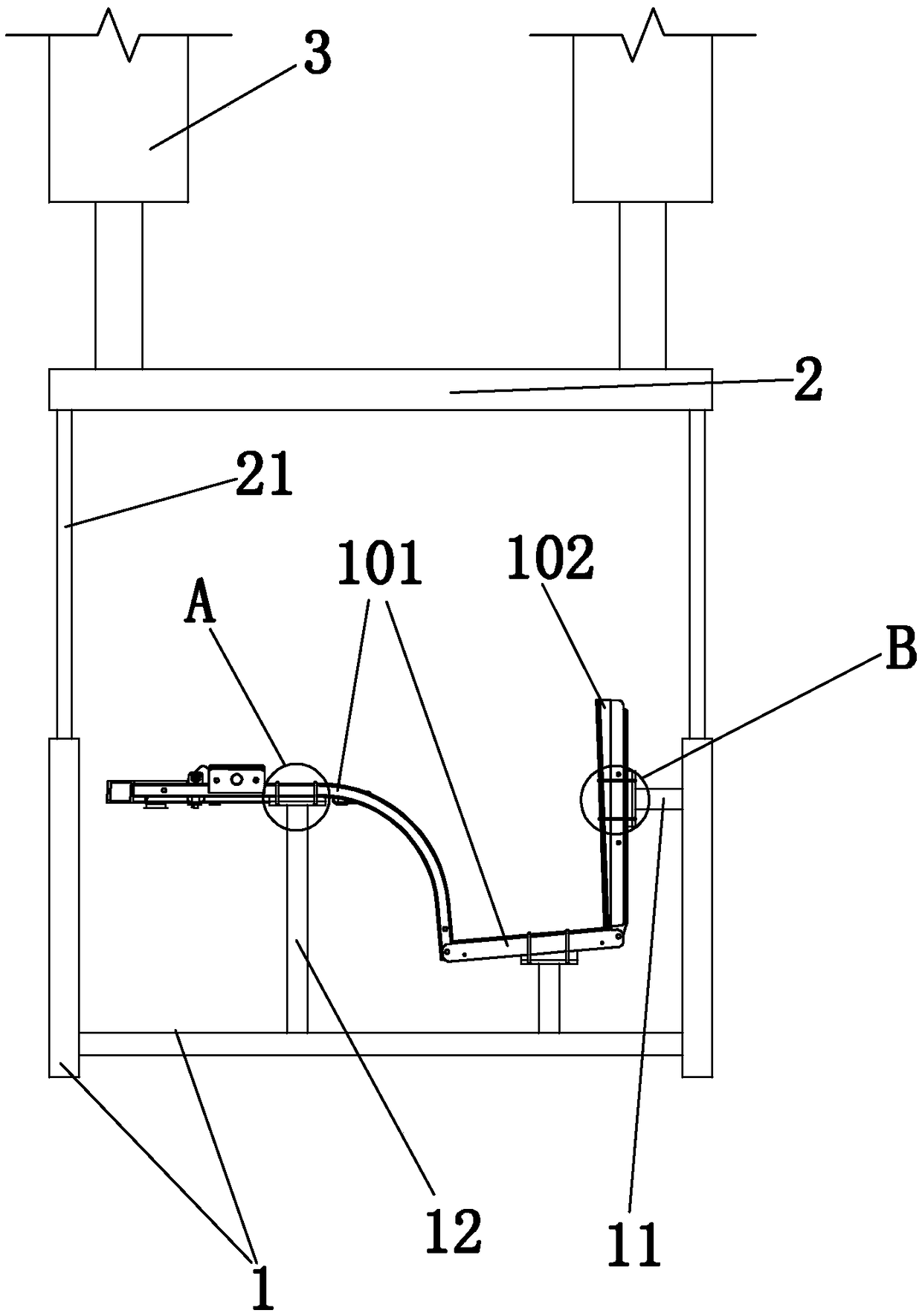
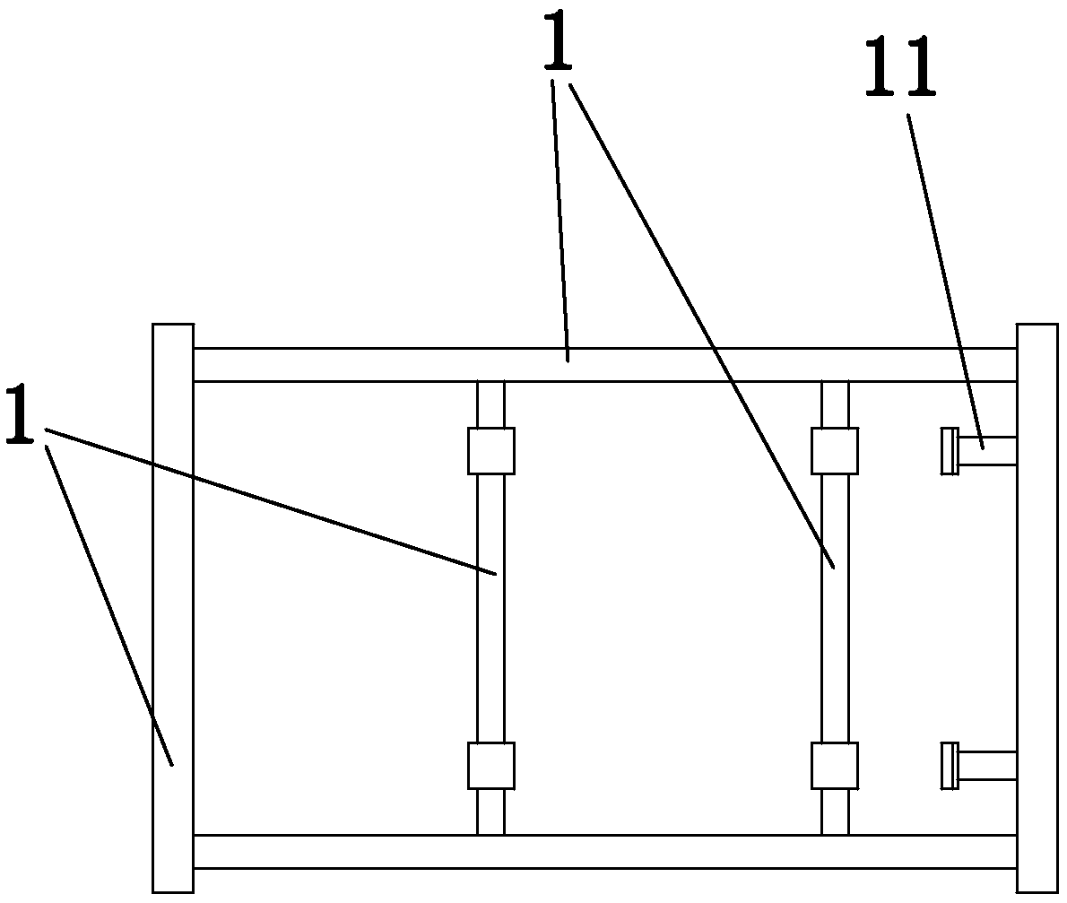
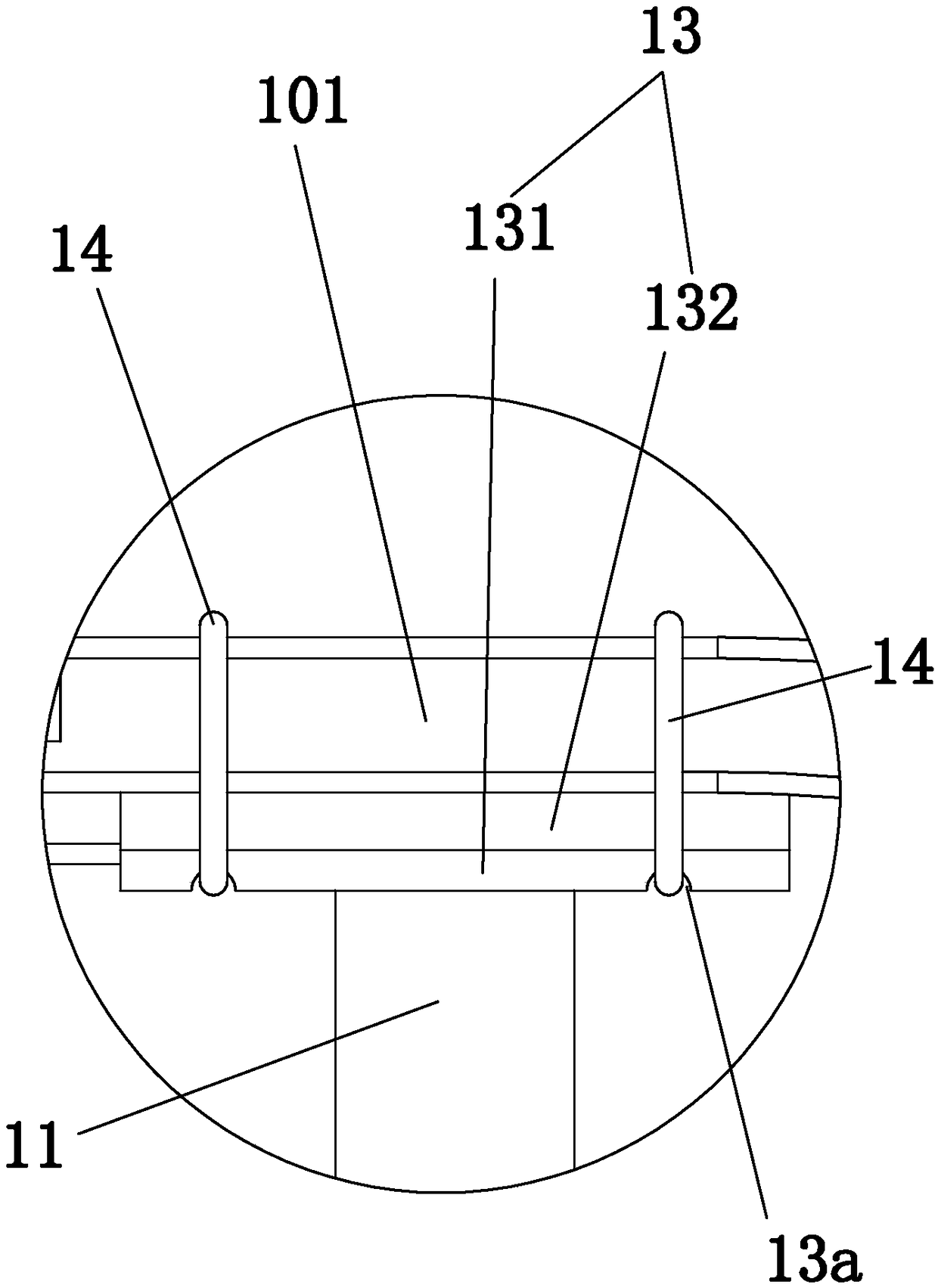
[0028] Embodiment 1: as figure 1 , figure 2 , image 3 , Figure 4 as shown in

[0029] A welding jig for a suspension type head seat bracket, comprising

[0030] Positioning frame 1, lifting frame 2 and several driving cylinders 3 for driving the lifting frame up and down;

[0031] The positioning frame is provided with some first fixing devices for fixing the front seat bracket and some second fixing devices for fixing the front pillar of the pedal. The first fixing device includes the first base rod 11, the parts support plate 13 and A plurality of straps 14, the second fixing device includes a second base rod 12, a component support plate 13 and a plurality of straps 14;

[0032] In a first fixing device: one end of the first base rod is connected to the positioning frame, the other end of the first base rod is connected to the part support plate, and the part support plate and the front seat bracket are bound by straps;

[0033] In a second fixing device: one end o...

Embodiment 2

[0040] Embodiment 2: based on embodiment 1, such as Figure 5 , Figure 6 as shown,

[0041] It also includes a number of welding dust cleaning devices arranged on the positioning frame and corresponding to the welding positions one by one. The welding dust cleaning device includes an air pump 4 and an air blowing pipe 5. In one welding dust cleaning device: the outlet of the air pump is connected to the inlet end of the air blowing pipe. The gas outlet end of the blowing tube faces the corresponding welding position. When welding for a certain welding position, the welding dust cleaning device corresponding to the welding position will blow air to quickly remove the welding dust (hereinafter referred to as impurities) at the welding position.

[0042] The welding dust cleaning device also includes a suction pipe 6 and a blanking pipe 7, the inlet of the air pump is connected to the outlet of the suction pipe, the inlet of the suction pipe is provided with a suction horn tub...


PUM


Abstract

The invention discloses a suspension type headstock chair bracket welding fixture. The suspension type headstock chair bracket welding fixture comprises a locating rack, a lifting stand, and a plurality of driving oil cylinders for driving the lifting stand to lift; a plurality of first fixing devices for fixing a headstock chair bracket are arranged on the locating rack and a plurality of secondfixing devices for fixing footboard front upright columns; the first fixing devices comprise first base rods, part supporting plates and a plurality of binding bands; the second fixing devices comprise second base rods, part supporting plates and a plurality of binding bands; and the lifting stand is located above and connected with the locating rack. The suspension type headstock chair bracket welding fixture has the beneficial effects that clamping location can be carried out effectively, and during clamping, an operating position is low, the clamping difficulty is low, the height is reasonable during welding and welding operation by a worker is facilitated.

Description

technical field [0001] The invention belongs to the technical field of vehicle processing, and in particular relates to a welding jig for a suspension type headstock seat bracket. Background technique [0002] During the vehicle production process, many components need to be welded, and the front frame, which is an important part of the vehicle, is no exception. The front seat bracket is a part of the front frame, which needs to be welded with some structures such as the front pillar of the pedal, and before welding, it needs to be clamped and positioned. However, due to the relatively low welding position between the front pillar of the pedal and the front seat bracket, it is inconvenient for workers to operate during welding; and if a higher clamp is used, the difficulty of clamping operation and greater labor intensity will be caused. . Contents of the invention [0003] The object of the present invention is to overcome the deficiencies in the prior art and provide a...

Claims


Application Information

Patent Timeline
Patent Type & Authority Applications(China)
IPC IPC(8): B23K37/04B23K37/00
CPCB23K37/00B23K37/0443
Inventor 刘桂祥李少良
Owner 浙江恒源机器有限公司
Why Eureka
Eureka Blog
Learn More