

Combined welding type water pump impeller and forming method thereof
A water pump impeller, welded technology, applied in welding equipment, non-variable pumps, pumps, etc., can solve the problems of difficult welding operation, affecting the efficiency of the water pump, and easy deformation of the blades, so as to achieve easy welding operation and no resistance in the flow path , The effect of simple welding and forming
- Summary
- Abstract
- Description
- Claims
- Application Information
AI Technical Summary
Problems solved by technology
Method used
Image

Examples
Embodiment Construction
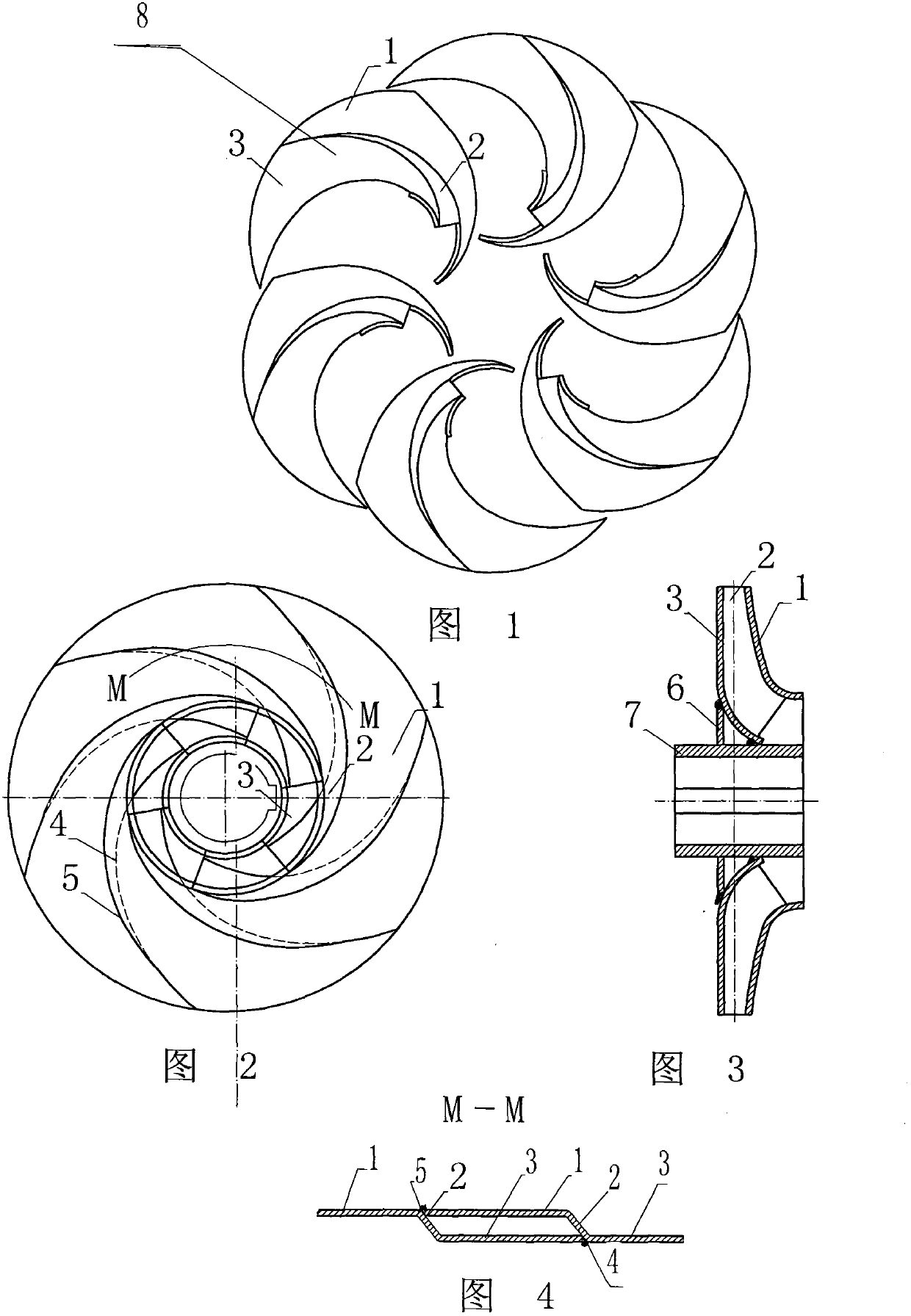
[0010] In the accompanying drawings, the combined welded water pump impeller of the present invention is welded by a hub 7, a reinforcing plate 6 and a plurality of impeller petals 8; The petal 1 is composed of the back cover petal 3, the blade 2, and the front cover petal 1, which are punched into a three-dimensional impeller petal 8 on a special mold by a plate; the edge line of each back cover petal 3 is connected with the other back cover petal The blade of each front cover flap is butted with the intersection line of the rear cover flap to form a rear weld 4, and the edge line of each front cover flap is docked with the intersection line of the blade of the other front cover flap and the front cover flap to form a front weld 5. Each impeller vane 8 is welded into a whole with a welding rod on the outside of the weld seam, and then the hub 7 and the reinforcement plate 6 are welded to obtain the welded impeller of the present invention.
PUM
 Abstract
Description
Claims
Application Information