Tool assembly for assisting in mounting elastic parts and elastic part mounting method

A technology of installation flexibility and installation method, which is applied in the direction of manufacturing tools, hand-held tools, etc., can solve problems such as time-consuming, labor-intensive, low work efficiency, and inconvenient installation methods

Pending Publication Date: 2021-02-02
HENGLIN HOME FURNISHINGS CO LTD
View PDF0 Cites 2 Cited by
  • Summary
  • Abstract
  • Description
  • Claims
  • Application Information

AI Technical Summary

Problems solved by technology

[0003] At present, the spring is installed on the both sides of the wooden frame on the rubber buckle hooks, generally the hook at one end of the spring is hung on the rubber buckle on one side of the wooden frame, and the manpower pulls the main body of the spring to close the other end. The hook part is hung on the rubber buckle on the other side of the wooden frame to complete the installation, but this installation method is time-consuming and labor-intensive, especially labor-intensive. To complete the installation of a spring, a large pulling force is required to deform the spring And hang it on the rubber buckle; figure 2 Therefore, a basic frame needs to be installed with multiple springs, and this installation method is extremely inconvenient and the work efficiency is low.

Method used


Image

  • Tool assembly for assisting in mounting elastic parts and elastic part mounting method
  • Tool assembly for assisting in mounting elastic parts and elastic part mounting method
  • Tool assembly for assisting in mounting elastic parts and elastic part mounting method

Examples


Embodiment 1

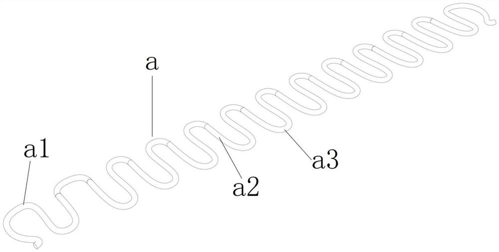
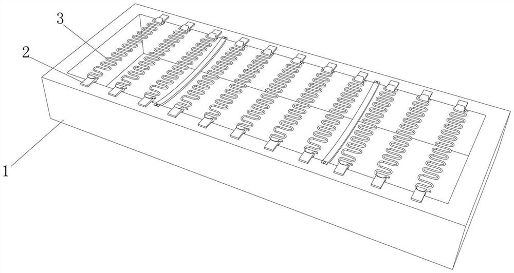
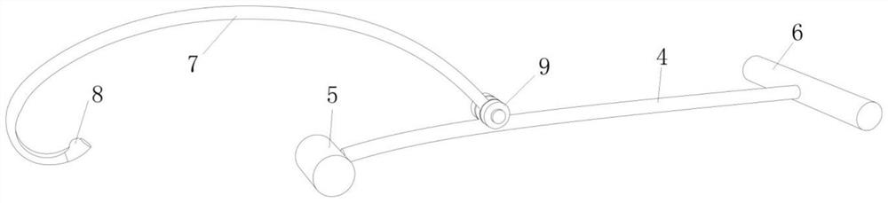
[0037] Referring to Figures 1 to 1 of the accompanying drawings in the description of the present invention Figure 7 As shown, according to a preferred implementation of the present invention, a tooling assembly for auxiliary installation of elastic members is described, the tooling assembly for auxiliary installation of elastic members 3 includes the tooling assembly including a support member 4 and a hook and pull member 7, the hook One end of the pulling member 7 is a hook-shaped structure, and the other end is hinged to the body of the supporting member 4; one end of the supporting member 4 is provided with a handle 6, and the other end is a supporting end 5 that provides a supporting point when the hook is pulled. The first distance value between the hinge point of the hook and pull member 7 and the support member 4 and the handle 6 is greater than the second distance value between the hinge point and the support end 5; in this embodiment, the elastic member 3 specificall...

Embodiment 2

[0042] This embodiment also provides a method for installing an elastic member, which is implemented by using the tooling assembly described in the first embodiment; specifically, the following steps are included:

[0043] Step 1: Hang the first end hook portion a1 of each elastic piece 3 in the rubber buckle 2 on the top of one end of the wooden frame 1;

[0044] Step 2: Hold the handle 6 with your hand, hook the hook-shaped end of the hook pulling member 7 to the second linear segment a2 at the end of the elastic member 3, and the supporting end 5 is against the side wall of the other end of the wooden frame 1 superior;

[0045] Step 3: With the contact point between the support end 5 and the side wall of the other end of the wooden frame 1 as the center, press the handle 6 downward, the support member 4 rotates around the contact point, and the elastic member 3 is deformed and elongated, so that the elastic member The end hook of 3 is hung on the rubber buckle 2 on the top...


PUM


Abstract

The invention aims to provide a tool assembly for efficiently assisting in mounting elastic parts and an elastic part mounting method. The tool assembly comprises a supporting part and a hooking and pulling part, wherein one end of the hooking and pulling part is of a hook-shaped structure, and the other end of the hooking and pulling part is hinged to a part body of the supporting part; a handleis arranged at one end of the supporting part, the other end of the supporting part serves as a supporting end for providing a supporting point during hooking, and a first distance value between a hinge point of the hooking part and the supporting part and the handle is greater than a second distance value between the hinge point and the supporting end; and the mounting speed is improved, and springs can be successfully mounted without consuming strength.

Description

technical field [0001] The invention relates to the field of home furnishing manufacturing and processing, in particular to a tooling assembly for auxiliary installation of elastic parts and an installation method of the elastic parts. Background technique [0002] When producing furniture, especially when producing elastic seats or elastic beds, springs need to be installed in the basic frame to enhance its elasticity. Since the current springs are no longer traditional springs, more such as figure 1 In the shown spring structure, the spring is flat as a whole, and the cross section of the spring is a certain arc. The spring includes a main body part and two hook parts. It includes multiple linear segments and multiple bending segments, and the same side of two adjacent linear segments is connected by a bending segment, such as figure 2 As mentioned above, generally an elastic seat or an elastic bed has a basic frame. The basic frame is formed by a rectangular wooden fram...

Claims


Application Information

Patent Timeline
Patent Type & Authority Applications(China)
IPC IPC(8): B25B27/30
CPCB25B27/30
Inventor 王江林
Owner HENGLIN HOME FURNISHINGS CO LTD
Why Eureka
Try Eureka