Pushing mechanism of wood processing device

A processing device and jacking technology, which is applied in the field of wood processing, can solve the problems of affecting work efficiency, prone to shaking, and labor-consuming, etc., and achieve the effect of good rotation effect and stable angle adjustment.

Inactive Publication Date: 2021-02-02
龙岩市企信工业设计有限公司
View PDF8 Cites 0 Cited by
  • Summary
  • Abstract
  • Description
  • Claims
  • Application Information

AI Technical Summary

Problems solved by technology

[0003] In the actual use process of the push mechanism of the wood processing device, because the angle of the wood is single when it is pushed in, the angle needs to be adjusted manually, which is more labor-intensive and affects the efficiency of the work; when the board is pushed out because only The left end is fixed, so it is easy to shake during the moving process, and the alignment in the processing device is not accurate

Method used


Image

  • Pushing mechanism of wood processing device
  • Pushing mechanism of wood processing device
  • Pushing mechanism of wood processing device

Examples


Embodiment 1

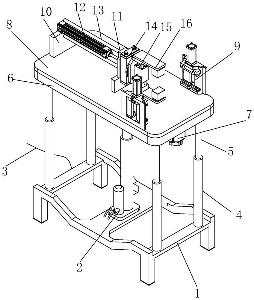
[0029] see figure 1 , the present invention provides a pushing mechanism of a wood processing device through improvement, including an underframe 1, an electric push rod 2 is installed in the middle of the top end of the underframe 1, a connecting wire 3 is provided at the left end of the bottom of the underframe 1, and the connecting wire 3 Electrically connected with the electric push rod 2, the top four ends of the bottom frame 1 are vertically fixed with a sleeve 4, the upper end of the sleeve 4 is movably embedded with a sliding rod 5, and a bearing plate 8 is arranged above the sliding rod 5, and the bottom right of the bearing plate 8 is installed There is a drive motor 7, and the drive motor 7 is electrically connected to the connection line 3. A support plate 10 is fixed on the left end of the top of the bearing plate 8, a support member 11 is installed on the right side of the support plate 10, and a cylinder 12 is arranged on the top of the support plate 10 and the s...

Embodiment 2

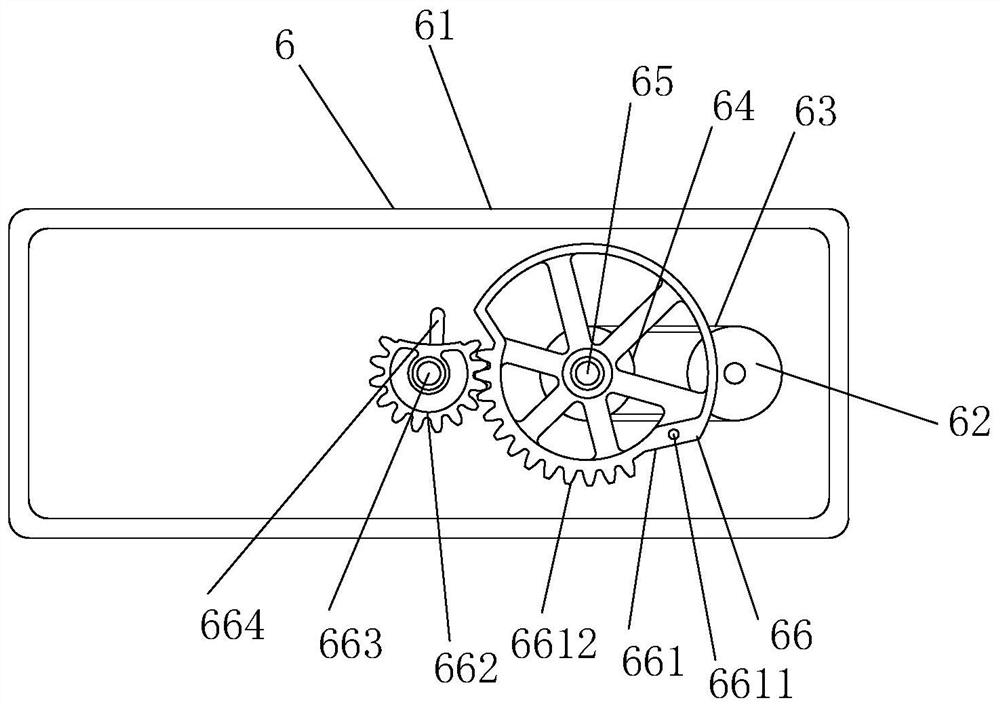
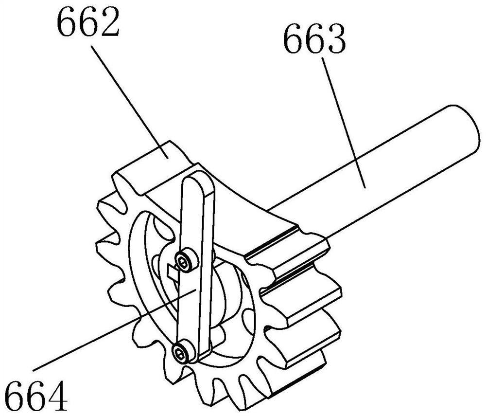
[0034] The present invention provides a pushing mechanism of a wood processing device through improvement. A sealing cover is installed in the middle of the bottom end of the housing 61, and the sealing cover is fixed to the housing 61 by bolts, which is convenient for users to check and maintain the inside; Two-thirds of the right end of the outer diameter surface of the rotating wheel 661 is arc-shaped, and the arc-shaped position is a smooth surface, which is convenient for rotation and has a good guiding effect; the contact surface between the top of the housing 61 and the bearing plate 8 is smooth, which is convenient for stabilizing Smooth rotation, good effect and strong stability.

[0035] The present invention provides a pushing mechanism of a wood processing device through improvement, and its working principle is as follows;

[0036] First, when the push mechanism needs to be used, first install the mechanism to the position where it needs to be installed on the woo...


PUM


Abstract

The invention discloses a pushing mechanism of a wood processing device. The pushing mechanism comprises an underframe, an electric push rod, a connecting wire, an adjusting device, a driving motor, abearing plate and anti-shaking devices. The adjusting device is mounted at the top of a sliding rod, and an intermittent rotating mechanism is mounted in the adjusting device and is driven by an independent motor; the bearing plate at the top rotates under driving, and stable adjustment of the angle and the position is achieved; the intermittent rotating mechanism is installed in the adjusting device and can stably and intermittently rotate under the control of the driving motor, the rotating effect is good, and stable angle adjustment of the bearing plate at the top is achieved; and the anti-shaking devices are installed at the front side and the rear side of the right end of the top of the bearing plate, the front end and the rear end of wood are arranged in the anti-shaking devices sothat the wood can be clamped, guiding and supporting are provided for the wood in the moving process, the clamping thickness can be adjusted in the anti-shaking devices, and thus the anti-shaking devices are suitable for wood of most thicknesses.

Description

technical field [0001] The invention relates to the related field of wood processing, in particular to a pushing mechanism of a wood processing device. Background technique [0002] Wood processing, using wood as raw material, is mainly processed by mechanical or chemical methods, and its products still maintain the basic characteristics of wood. In the forest industry, wood processing industry and chemical processing of forest products are both follow-up industries of forest harvesting and transportation. In the important department of comprehensive utilization of resources, when the wood processing device is actually used, it is necessary to install a special pushing mechanism to lift the wood and push it into the processing device for stable processing. [0003] In the actual use process of the push mechanism of the wood processing device, because the angle of the wood is single when it is pushed in, the angle needs to be adjusted manually, which is more labor-intensive a...

Claims


Application Information

Patent Timeline
Patent Type & Authority Applications(China)
IPC IPC(8): B27C9/00
CPCB27C9/00
Inventor 郑瑞盛
Owner 龙岩市企信工业设计有限公司
Why Eureka
Try Eureka