Circuit board four-wire test system and test method
A technology of testing system and testing method, which is applied in the direction of electronic circuit testing, printed circuit testing, electrical measurement, etc., and can solve the problems of testing PTH hole resistance, unable to set test needles, etc.
Pending Publication Date: 2021-02-02
KINWONG ELECTRONIC TECH (ZHUHAI) CO LTD
0 Cites 0 Cited by
AI-Extracted Technical Summary
Problems solved by technology
However, when the width of the annular ring of the PTH hole is too small, for example, the annular ring is less than 0.12mm, the test nee...
Method used
In the above-mentioned circuit board four-wire testing method, two first test pins 21 are respectively connected to the first annular ring 111 and the second annular ring 112, and two second test pins 22 are respectively connected to the first test pad 13 and the second test pad 13. Two test pads 14, while the first annular ring 111 and the first test pad 13 are conducting, and the second annular ring 112 is conducting with the second testing pad 14. Therefore, the above-mentioned circuit board four-wire testing method does not need to The four test pins are all set on the annular ring, which solves the problem that the test pins cannot be set due to the small width of the annular ring, so that the first through hole can be measured through two first test pins 21 and two second test pins 22 11 to detect the conduction performance of the first through hole 11. At the same time, since the two first test pins 21 are respectively arranged on both sides of the first through hole 11, the measu...
Abstract
The invention is applicable to the technical field of circuit board testing, and provides a circuit board four-wire testing system. The system comprises a circuit board and a four-wire testing module;a first through hole is formed in the circuit board, and a first hole ring and a second hole ring are arranged at the two ends of the first through hole respectively; a first test bonding pad and a second test bonding pad are respectively arranged on two sides of the circuit board, the first test bonding pad is conducted with the first hole ring, and the second test bonding pad is conducted withthe second hole ring; the four-wire test module comprises two first test pins and two second test pins, the two first test pins are connected with the first hole ring and the second hole ring respectively and used for testing the voltage of the first through hole, and the two second test pins are connected with the first test bonding pad and the second test bonding pad respectively and used for applying constant current to the first through hole. The circuit board four-wire test system can accurately test the resistance of the through holes in the circuit board. The invention also provides a circuit board four-wire test method.
Application Domain
Printed circuit testing
Technology Topic
EngineeringStructural engineering +3
Image
Examples
- Experimental program(1)
Example Embodiment
[0041]In order to make the objectives, technical solutions, and advantages of the present invention clearer, the present invention will be further described in detail below in conjunction with the accompanying drawings, namely embodiments. It should be understood that the specific embodiments described here are only used to explain the present invention, but not to limit the present invention.
[0042]It should be noted that when a component is referred to as being "fixed to" or "installed on" another component, it can be directly or indirectly on the other component. When a component is said to be "connected" to another component, it can be directly or indirectly connected to the other component. The terms "upper", "lower", "left", "right", etc. indicate the orientation or positional relationship based on the orientation or positional relationship shown in the drawings, and are only for ease of description, and do not indicate or imply the device referred to. Or the element must have a specific orientation, be constructed and operated in a specific orientation, and therefore cannot be understood as a restriction on patents. The terms "first" and "second" are only used for ease of description, and cannot be understood as indicating or implying relative importance or implicitly indicating the number of technical features. The meaning of "plurality" means two or more than two, unless otherwise specifically defined.
[0043]In order to illustrate the technical solution of the present invention, the following description will be given in conjunction with specific drawings and embodiments.
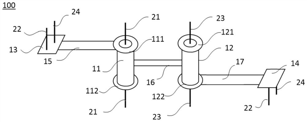
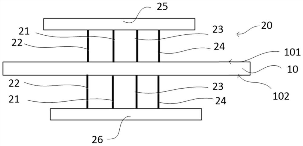
[0044]Please also refer tofigure 1 withfigure 2 The embodiment of the present application provides a circuit board four-wire test system 100, which includes a circuit board 10 and a four-wire test module 20.
[0045]The circuit board 10 is provided with a first through hole 11, both ends of the first through hole 11 are respectively provided with a first eye ring 111 and a second eye ring 112, and the first eye ring 111 and the second eye ring 112 are electrically connected. In one embodiment, the first through hole 11 is a PTH hole, and the first ring 111 and the second ring 112 are electrically connected by the conductive material in the first through hole 11, for example, the first ring 111 and The second ring 112 is electrically connected by copper plating in the first through hole 11.
[0046]A first test pad 13 and a second test pad 14 are respectively provided on both sides of the circuit board 10. The first test pad 13 is connected to the first ring 111, and the second test pad 14 is connected to the second test pad. The ring 112 is connected.
[0047]The four-wire test module 20 includes two first test pins 21 and two second test pins 22. The two first test pins 21 are respectively connected to the first ring 111 and the second ring 112 and are used to test the first test pin. The voltage of the hole 11, the two second test pins 22 are respectively connected to the first test pad 13 and the second test pad 14 and are used to apply a constant current to the first through hole 11. Therefore, it can be measured by the current value and Calculate the resistance of the first through hole 11 to detect whether the first through hole 11 is conductive, and whether there are defects such as too thin copper and no copper in the hole.
[0048]In the circuit board four-wire test system 100, the two first test pins 21 are connected to the first ring 111 and the second ring 112, and the two second test pins 22 are connected to the first test pad 13 and the second test. At the same time, the first hole ring 111 and the first test pad 13 are connected, and the second hole ring 112 and the second test pad 14 are connected. Therefore, the four-wire circuit board test system 100 does not need to connect four The test pins are all set on the eye ring, which solves the problem that the test pins cannot be set due to the small width of the eye ring, so that the first through hole 11 can be measured through the two first test pins 21 and the two second test pins 22 Voltage to detect the resistance of the first through hole 11.
[0049]At the same time, since the two first test pins 21 are respectively provided on both sides of the first through hole 11, the resistance measured by the four-wire circuit board test system 100 does not include the resistance of the circuit, and only the resistance of the first through hole 11 is retained. , To ensure the accuracy of the test. Therefore, the circuit board four-wire testing system 100 can accurately test the resistance of the through holes in the circuit board 10.
[0050]Specifically, the circuit board 10 includes a first surface 101 and a second surface 102 disposed oppositely, and the first test pad 13 and the second test pad 14 are respectively disposed on the first surface 101 and the second surface 102.
[0051]The first annular ring 111 is connected to the first test pad 13 through the first outer circuit 15 provided on the first surface 101; the second annular ring 112 passes through the inner circuit 16 in the circuit board 10 and is arranged on the The second outer layer circuit 17 on the two surfaces 102 is connected to the second test pad 14. In this way, the first orifice ring 111 and the second orifice ring 112 can be respectively connected to the first test pad 13 and the second test pad 14, so that a first test pin 21 and a second test pin 22 are a group , Respectively connect the first test pad 13 and the first ring 111, the other first test pin 21 and the other second test pin 22 are a group, respectively connect the second test pad 14 and the second ring 112, Meet the requirements of four-wire test. The circuit board four-wire test system 100 can be applied to the case where the test pad is not provided at the first through hole 11 and the ring width is small.
[0052]In one embodiment, the circuit board 10 is a multilayer circuit board; it can be understood that in other embodiments, the circuit board 10 may also be a double-sided circuit board. In this case, the rings at both ends of the first through hole 11 can pass through the outer The layer circuit is connected to the first test pad 13 and the second test pad 14 without the need of an inner layer circuit.
[0053]In one embodiment, the width of the first orifice ring 111 and the second orifice ring 112 is relatively small, for example, less than 0.12 mm in width, and the ends of the two first test pins 21 are respectively disposed in the middle of the first through hole 11 and contact with each other. The inner ring of the first through hole 11, the inner ring may be copper plated in the first through hole 11, so that the first test pin 21 can still contact the copper plated in the first through hole 11 to connect to the An orifice ring 111 or a second orifice ring 112. Preferably, the end of the first test needle 21 is tapered.
[0054]In one embodiment, the diameter of the end of the first test needle 21 is larger than the aperture of the first through hole 11, that is, the edge of the tapered end can contact the inner ring of the first through hole 11, so that the first test needle 21 is connected to the first through hole 11.
[0055]In an embodiment, the circuit board 10 is further provided with a second through hole 12, and the two ends of the second through hole 12 are respectively provided with a third eye ring 121 and a fourth eye ring 122, the third eye ring 121 and the fourth eye ring The aperture ring 122 is connected.
[0056]The four-wire test module 20 also includes two third test pins 23 and two fourth test pins 24. The two third test pins 23 are respectively connected to the third ring 121 and the fourth ring 122, and two fourth test pins. The pins 24 are connected to the first test pad 13 and the second test pad 14 respectively.
[0057]Among them, the third annular ring 121 is connected to the first test pad 13 through the inner circuit 16 and the first outer circuit 15; the fourth annular ring 122 is connected to the second test pad 14 through the second outer circuit 17 Conduction.
[0058]In this embodiment, the two third test pins 23 are used to test the voltage of the second through hole 12, and the two fourth test pins 24 are used to apply a constant current to the second through hole 12. The circuit board four-wire test system 100 can test the resistance of the first through hole 11 and the second through hole 12 at the same time.
[0059]It can be understood that in other embodiments, the two fourth test pins 24 may also be connected to other pads other than the first test pad 13 and the second test pad 14.
[0060]Since the two third test pins 23 are respectively arranged on both sides of the second through hole 12, when testing the resistance of the second through hole 12, the resistance includes only the resistance of the second through hole 12, and does not include the first outer layer The resistance of the circuit 15, the second outer circuit 17 or the inner circuit 16, therefore, the circuit board four-wire test system 100 can test the resistance of the second through hole 12 and filter out the influence of other circuits, and the test is more accurate.
[0061]In one embodiment, when the widths of the third or fourth orifice ring 121 and 122 are relatively small, the ends of the two third test pins 23 are respectively arranged in the middle of the second through hole 12 and contact the second through hole 12的内环。 The inner ring. In this way, the third test pin 23 can still contact the copper plating in the second through hole 12. Preferably, the end of the third test needle 23 may be tapered.
[0062]In an embodiment, the circuit board four-wire testing system 100 further includes a first test rack 25 and a second test rack 26 respectively arranged on both sides of the circuit board 10. A first test pin 21, a second test pin 22, a third test pin 23, and a fourth test pin 24 are arranged on the first test frame 25 and contact the first surface 101 of the circuit board 10; The test pin 21, another second test pin 22, another third test pin 23 and another fourth test pin 24 are arranged on the second test frame 26 and contact the second surface 102 of the circuit board 10.
[0063]Among them, the two first test pins 21 are respectively connected to the voltage test input end (not shown) of the four-wire test module 20 through the first test frame 25 and the second test frame 26; the two second test pins 22 respectively pass through the A test frame 25 and a second test frame 26 are connected to the current test input end of the four-wire test module 20 (not shown).
[0064]Similarly, the two third test pins 23 are respectively connected to the voltage test input terminals of the four-wire test module 20 through the first test frame 25 and the second test frame 26; the two fourth test pins 24 respectively pass through the first test frame 25 The current test input terminal of the four-wire test module 20 is connected to the second test frame 26.
[0065]It can be understood that in addition to the first test pin 21, the first test frame 25 is also provided with multiple test pins; in addition to the second test pin 22, the second test frame 26 is also provided with multiple test pins. The "first", "second", "third", and "fourth" mentioned herein are only used for ease of description. In the actual test, it is sufficient to select the test pin on the first test frame 25 to be connected to the corresponding hole ring or test pad.
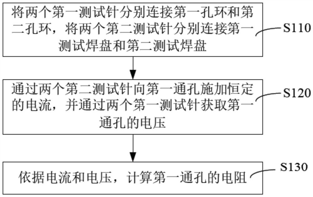
[0066]This application also proposes a circuit board four-wire test method, which is suitable for the above-mentioned circuit board four-wire test system 100, please refer toFigure 1 to Figure 3, The circuit board four-wire test method includes the following steps.
[0067]S110: Connect the two first test pins 21 to the first orifice ring 111 and the second orifice ring 112 respectively, and connect the two second test pins 22 to the first test pad 13 and the second test pad 14 respectively.
[0068]S120: Apply a constant current to the first through hole 11 through the two second test pins 22, and obtain the voltage of the first through hole 11 through the two first test pins 21.
[0069]S130: Calculate the resistance of the first through hole 11 according to the voltage and current.
[0070]Specifically, the resistance of the first through hole 11 is calculated by the following formula:
[0071]R=U/I
[0072]Among them, R is the resistance to be measured, U is the voltage obtained by the test, and I is the current applied to the first through hole 11.
[0073]The test result of the foregoing four-wire test method for the circuit board only retains the resistance of the first through hole 11, and is not affected by the line resistance, which improves the accuracy of the detection.
[0074]In an embodiment, the circuit board 10 includes a first through hole 11 and a second through hole 12 at the same time, and the four-wire test method for the circuit board further includes the following steps.
[0075]In step S110, the two third test pins 23 are connected to the first orifice ring 111 and the second orifice ring 112 respectively, and the two fourth test pins 24 are respectively connected to the first test pad 13 and the second test pad. 14.
[0076]In step S120, a constant current is simultaneously applied to the first through hole 11 through the two fourth test pins 24, and the voltage of the second through hole 12 is obtained through the two third test pins 23.
[0077]In step S130, the resistance of the second through hole 12 is calculated at the same time.
[0078]It can be understood that in other embodiments, the two fourth test pins 24 may also be connected to other pads other than the first test pad 13 and the second test pad 14.
[0079]In the above four-wire test method for the circuit board, the two first test pins 21 are respectively connected to the first ring 111 and the second ring 112, and the two second test pins 22 are respectively connected to the first test pad 13 and the second test solder. At the same time, the first perforated ring 111 and the first test pad 13 are connected, and the second perforated ring 112 and the second test pad 14 are connected. Therefore, the four-wire test method for the circuit board does not require four tests. The needles are all arranged on the orifice ring, which solves the problem that the test needle cannot be arranged due to the small width of the orifice ring, so that the voltage of the first through hole 11 is measured through the two first test pins 21 and the two second test pins 22 , To detect the conduction performance of the first through hole 11. At the same time, since the two first test pins 21 are respectively arranged on both sides of the first through hole 11, the measured resistance does not include the resistance of the first outer layer line 15, the second outer layer line 17, or the inner layer line 16, only The resistance of the first through hole 11 is retained, which improves the accuracy of the test. Therefore, the above-mentioned circuit board four-wire test system and test method can accurately test the resistance of the through holes in the circuit board 10.
[0080]The above embodiments are only used to illustrate the technical solutions of the application, not to limit them; although the application has been described in detail with reference to the foregoing embodiments, a person of ordinary skill in the art should understand that: The recorded technical solutions are modified, or some of the technical features are equivalently replaced; and these modifications or replacements do not cause the essence of the corresponding technical solutions to deviate from the spirit and scope of the technical solutions of the embodiments of this application, and should be included in this application Within the scope of protection.
PUM


Description & Claims & Application Information
We can also present the details of the Description, Claims and Application information to help users get a comprehensive understanding of the technical details of the patent, such as background art, summary of invention, brief description of drawings, description of embodiments, and other original content. On the other hand, users can also determine the specific scope of protection of the technology through the list of claims; as well as understand the changes in the life cycle of the technology with the presentation of the patent timeline. Login to view more.