
Micro-mirror structure and manufacturing method thereof, micro-mirror array and detector

A manufacturing method and micromirror technology, which are applied in the field of micromirror arrays and detectors, can solve the problems of increasing the difficulty of control and meeting the wide range of requirements for the deflection direction of the micromirror, and achieve simple structure, precise and convenient angle control, and satisfy multiple requirements. effect of demand

Pending Publication Date: 2021-02-02
SHANGHAI INST OF TECHNICAL PHYSICS - CHINESE ACAD OF SCI
View PDF5 Cites 4 Cited by
  • Summary
  • Abstract
  • Description
  • Claims
  • Application Information

AI Technical Summary

Problems solved by technology

However, when adjusting the deflection angle of the micromirror through electrostatic field control, it is often necessary to design a very complicated deflection structure, such as a comb structure, which undoubtedly increases the difficulty of control, and it can only make the micromirror plane along a fixed Axial deflection, so it is difficult to meet the wide range of requirements for the deflection direction of the micromirror in actual use scenarios

Method used


Image

  • Micro-mirror structure and manufacturing method thereof, micro-mirror array and detector
  • Micro-mirror structure and manufacturing method thereof, micro-mirror array and detector
  • Micro-mirror structure and manufacturing method thereof, micro-mirror array and detector

Examples


Embodiment Construction

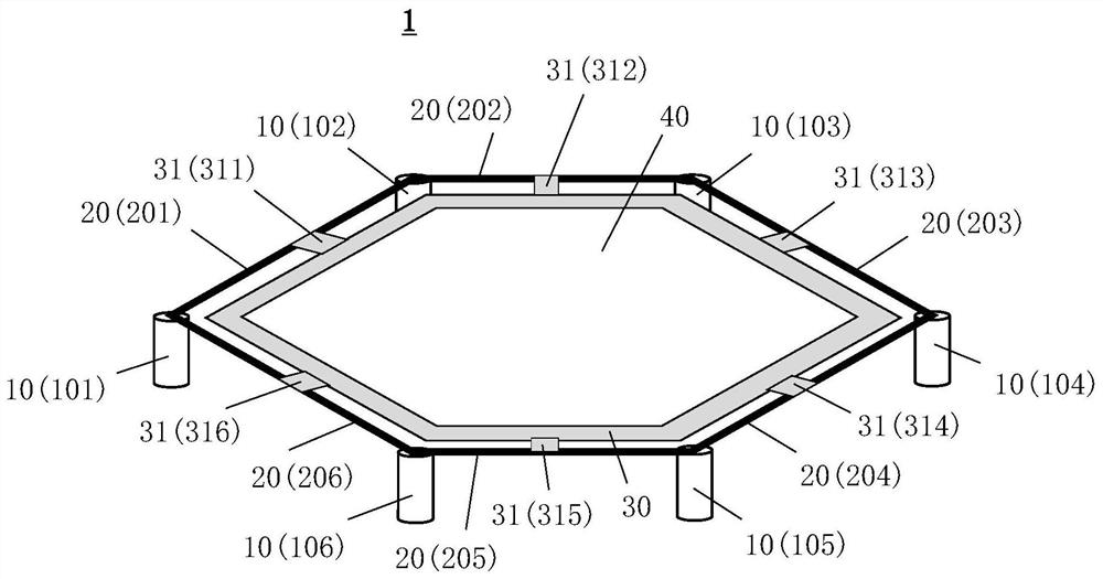
[0037] The core idea of ​​the present invention is that the present invention provides a hexagonal micromirror structure, using a six-section deformable beam structure that can produce bending deformation after being energized and heated, as a power mechanism for driving the deflection of the hexagonal micromirror (light reflection film) , and the displacement of the side can be controlled in sections from different sides of the six sides of the micromirror, so the present invention can be used to deflect the micromirror towards any predetermined direction, and can also control the micromirror as a whole in the vertical direction Floating on the surface, which greatly meets the various requirements for the deflection (movement) direction of the micromirror in different application scenarios. Compared with complex deflection control structures such as the comb structure in the prior art, the present invention uses six deformable beam structures to adjust the deflection angle of ...


PUM


Abstract

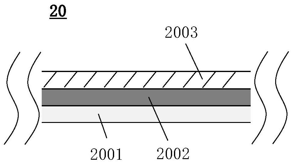
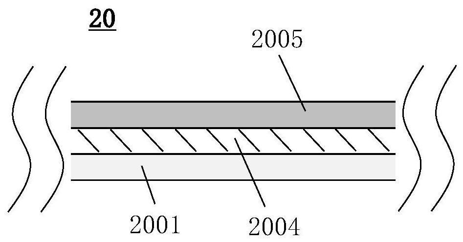
The invention discloses a micro-mirror structure, which comprises the components of a hexagonal light reflecting film which is suspended on a substrate; six sections of deformation beams sequentiallysurround the outer side or the lower side of the light reflecting film in an end-to-end adjacent or connected mode, and each section of deformation beam is connected to the outer side of one corresponding edge of the light reflecting film in an insulating mode through a fulcrum structure; and six supporting columns are respectively supported below adjacent or connected endpoints of every two sections of deformation beams; at least one section of deformation beam is electrified, so that the deformation beam generates bending deformation in the upward or downward direction relative to the lengthdirection of the deformation beam due to electrification and heating, the corresponding edge of the light reflection film connected with the deformation beam is driven to move upwards or downwards, and different combinations of deformation sizes formed by respectively controlling the deformation beams are executed. The deflection or / and up-down floating of the light reflecting film towards any preset direction is / are achieved. The invention further discloses a manufacturing method of the micro-mirror structure, a micro-mirror array and a detector.

Description

technical field [0001] The invention relates to the technical field of semiconductor integrated circuits and detectors, in particular to a micromirror structure capable of deflecting in any direction, a manufacturing method thereof, a micromirror array and a detector. Background technique [0002] At present, micromirrors have become an important member of micro-electromechanical systems (MEMS) products, and have begun to be used in vehicle-mounted laser radars. With the development of autonomous driving technology, higher and higher requirements are placed on lidar and its MEMS micromirror technology. [0003] Among them, it has become a relatively mature technology to realize the control of the deflection angle of the micromirror by means of electrostatic driving. However, when adjusting the deflection angle of the micromirror through electrostatic field control, it is often necessary to design a very complicated deflection structure, such as a comb structure, which undou...

Claims


Application Information

Patent Timeline
Patent Type & Authority Applications(China)
IPC IPC(8): G02B26/08G02B17/00G02B17/06
CPCG02B26/0833G02B17/0668G02B17/006
Inventor 程正喜徐鹤靓陈永平
Owner SHANGHAI INST OF TECHNICAL PHYSICS - CHINESE ACAD OF SCI
Learn More