
Socket

A technology of sockets and plugs, which is applied in the direction of electrical components, coupling devices, circuits, etc., and can solve problems such as damage to electrical equipment, electric shock to staff, and large fluctuations in socket current.

Active Publication Date: 2021-02-02
GUANGDONG POWER GRID CO LTD +1
View PDF6 Cites 0 Cited by
  • Summary
  • Abstract
  • Description
  • Claims
  • Application Information

AI Technical Summary

Problems solved by technology

However, in the process of using the socket, the plug will be pulled because the connecting wire of the electrical equipment is too short. Use and lifespan of electrical equipment
Especially when the air is humid, the current of the socket fluctuates greatly, and it is very easy to generate arcs and flashovers, resulting in damage to electrical equipment or the consequences of electric shock to staff

Method used


Image

  • Socket
  • Socket
  • Socket

Examples


Embodiment 1

[0042] This embodiment provides a socket, which is used to supply power to or cut off power for electric equipment, so as to improve the safety of electric equipment.

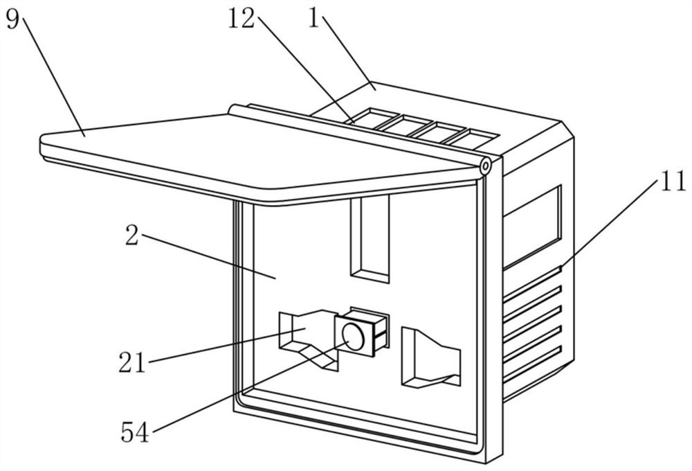
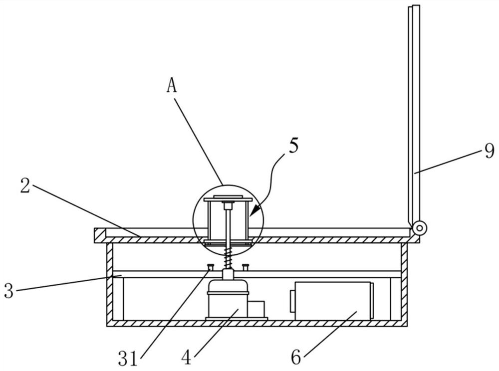
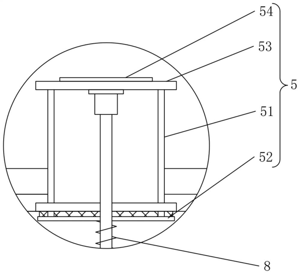
[0043] Such as figure 1 and figure 2 As shown, the socket provided in this embodiment includes a socket body 1 , a first plate 2 , a thrust mechanism and a current sensor 6 . Wherein, the socket main body 1 has a receiving groove, and the first plate 2 covers the opening of the receiving groove, and the plug of the electrical equipment passes through the first plate 2 and is electrically connected to the power module of the device main body 1 . The push mechanism includes an electromagnetic push rod 4 and a pop-up assembly 5, the electromagnetic push rod 4 is arranged in the receiving groove, the pop-up assembly 5 is connected to the output end of the electromagnetic push rod 4, and the pop-up assembly 5 slides through the first plate 2, To switch between the ejection position and the avoidance position, whe...

Embodiment 2

[0057] Such as figure 1 As shown, the socket of the second embodiment is basically the same as that of the first embodiment above. The difference between the two is that the socket also includes cooling holes 11, which can prevent the socket from being overheated during use and causing danger.

[0058] Specifically, the cooling hole 11 is provided on one side of the socket main body 1 to dissipate the heat of the socket and prevent the internal temperature of the socket from being too high.

[0059] Such as figure 1 As shown, in order to keep the dryness of the socket, preferably, one end of the first board 2 is rotatably connected with a board cover 9, and the board cover 9 can be rotated to cover the first board 2, and the first board 2 is blocked by the board cover 9 , can reduce the external environment such as the attachment and condensation of humid air on the first board 2, and keep the first board 2 dry for a long time. In order to ensure the tightness between the pl...


PUM


Abstract

The invention relates to the technical field of power equipment, and particularly discloses a socket, which comprises a socket main body, a first plate, an abutting and pushing mechanism and a currentsensor, wherein the socket main body is provided with an accommodating groove, the first plate covers the opening of the accommodating groove, a plug of electric equipment penetrates through the first plate and is electrically connected with the electrifying module of the socket main body, the abutting and pushing mechanism comprises an electromagnetic push rod and a bouncing assembly, the electromagnetic push rod is arranged in the accommodating groove, the bouncing assembly is connected to the output end of the electromagnetic push rod, the bouncing assembly is arranged on the first plate in a sliding and penetrating mode so as to be switched between an ejection position and a receding position, and when the bouncing assembly is switched from the receding position to the ejection position, the bouncing assembly drives the plug to be separated from the electrifying module and the first plate, and the electric equipment and the socket are powered off, so that the damage of the electric equipment is avoided, and the probability of electric shock of workers is reduced.

Description

technical field [0001] The invention relates to the field of electric equipment, in particular to a socket. Background technique [0002] Socket claims again supply socket and combined socket and switch, and socket has referred to the insertable seat of one or more circuit connections, can insert the plug of various wiring electrical equipment by it, makes the electrical equipment connected be energized. However, in the process of using the socket, the plug will be pulled because the connecting wire of the electrical equipment is too short. The use and life of electrical equipment. Especially when the air is humid, the current of the socket fluctuates greatly, which is very easy to generate arcs and flashovers, resulting in damage to electrical equipment or the consequences of electric shock to staff. Contents of the invention [0003] An object of the present invention is to provide a socket to avoid the phenomenon that the plug of the electrical equipment is still elec...

Claims


Application Information

Patent Timeline
Patent Type & Authority Applications(China)
IPC IPC(8): H01R13/635H01R13/66
CPCH01R13/635H01R13/6683H01R13/66
Inventor 郑文智张文怡钟月荣邱嘉杰林宇扬李通
Owner GUANGDONG POWER GRID CO LTD
Learn More