
Camera module, shooting control method and electronic equipment

A camera module, shooting mode technology, applied in the field of electronics, can solve the problems such as the eccentricity of the opening of the lens and decorative parts

Active Publication Date: 2021-02-02
VIVO MOBILE COMM CO LTD
View PDF7 Cites 3 Cited by
  • Summary
  • Abstract
  • Description
  • Claims
  • Application Information

AI Technical Summary

Problems solved by technology

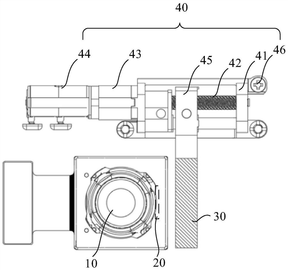
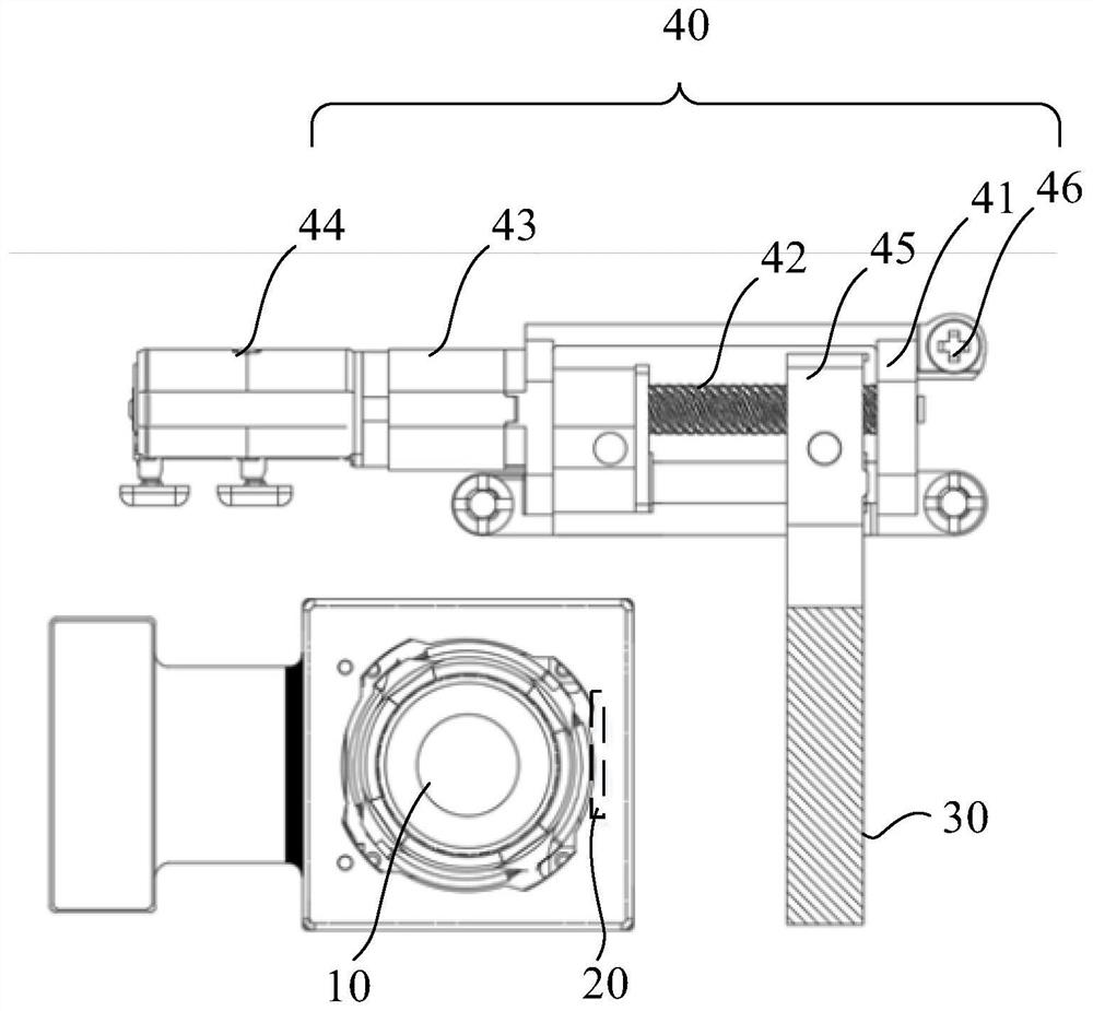
[0005] The purpose of the embodiments of the present application is to provide a shooting control method that can solve the problem of eccentricity of the opening of the lens and the decorative part due to the movement of the lens

Method used


Image

  • Camera module, shooting control method and electronic equipment
  • Camera module, shooting control method and electronic equipment
  • Camera module, shooting control method and electronic equipment

Examples


Embodiment Construction

[0022] The following will clearly and completely describe the technical solutions in the embodiments of the present application with reference to the drawings in the embodiments of the present application. Obviously, the described embodiments are part of the embodiments of the present application, not all of them. Based on the embodiments in this application, all other embodiments obtained by persons of ordinary skill in the art without creative efforts fall within the protection scope of this application.

[0023] The terms "first", "second" and the like in the specification and claims of the present application are used to distinguish similar objects, and are not used to describe a specific sequence or sequence. It should be understood that the terms so used are interchangeable under appropriate circumstances such that the embodiments of the application can be practiced in sequences other than those illustrated or described herein, and that references to "first," "second," et...


PUM


Abstract

The invention discloses a camera module, a shooting control method and electronic equipment, belongs to the technical field of electronics, and aims to solve the problem of eccentricity of openings ofa lens and a decorative part caused by movement of the lens. The camera module comprises a lens; a first magnet connected with the lens; a second magnet opposite to the first magnet, wherein the first magnet and the second magnet are located on the same side of the lens; a driving mechanism connected with the second magnet; a control mechanism connected with the driving mechanism, wherein the control mechanism is used for controlling the driving mechanism to drive the second magnet to be away from the first magnet under the condition that the camera module starts a shooting mode until the lens is in an active state. Under the condition that the camera module closes the shooting mode, the driving mechanism is controlled to drive the second magnet to get close to the first magnet until thelens is in a static state. The camera module disclosed in the application is applied to the electronic equipment.

Description

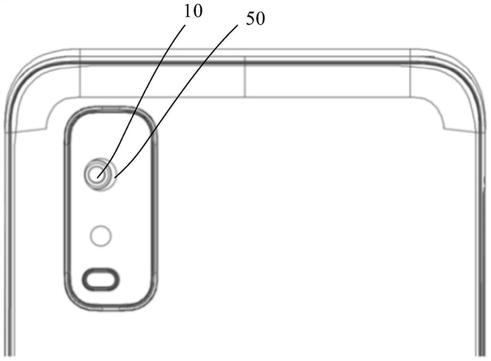
technical field [0001] The application belongs to the field of electronic technology, and in particular relates to a camera head module, a shooting control method and electronic equipment. Background technique [0002] The existing electronic equipment includes a lens and a decorative part, the decorative part is provided with a hole, and the center line of the lens coincides with the center line of the hole. With the gradual improvement of people's shooting requirements, the lens can be fine-tuned during the shooting process to achieve the anti-shake effect. [0003] In the non-shooting state, the lens is in a free state, and it is easy to move the lens, which will cause the lens and the opening to be off-center, and affect the aesthetics of the appearance. [0004] Therefore, during the process of implementing the present application, the inventors have found at least the following problems in the prior art: the lens and the opening of the decorative part are off-centered...

Claims


Application Information

Patent Timeline
Patent Type & Authority Applications(China)
IPC IPC(8): H04N5/225H04N5/232
CPCH04N23/54H04N23/663H04N23/57H04N23/55
Inventor 邓浩
Owner VIVO MOBILE COMM CO LTD
Learn More