Energy-saving electronic cable winding device

A technology of winding device and cable, applied in the directions of transportation and packaging, transportation of filamentous materials, thin material processing, etc., can solve the problems of complicated device, inconvenient to popularize and implement, increase manufacturing and production cost, etc. The effect of simplification, easy promotion and implementation, and reduction of manufacturing and production costs

Active Publication Date: 2020-03-24
GUANYUN POWER SUPPLY OF JIANGSU ELECTRIC POWER
View PDF12 Cites 6 Cited by
  • Summary
  • Abstract
  • Description
  • Claims
  • Application Information

AI Technical Summary

Problems solved by technology

The device uses multiple sets of motors for winding and wiring, which complicates the device, increases manufacturing and production costs, and is not easy to popularize and implement

Method used


Image

  • Energy-saving electronic cable winding device
  • Energy-saving electronic cable winding device
  • Energy-saving electronic cable winding device

Examples


Embodiment 1

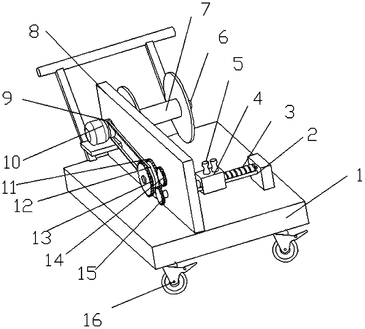
[0024] see Figure 1-2 , an energy-saving electronic cable winding device, comprising a base 1 and a cable roller 7, the four corners of the bottom of the base 1 are provided with universal wheels 16, the universal wheels 16 are provided with clamping plates, and the clamping plates have Braking effect, the setting of universal wheel 16 facilitates the movement and fixing of base 1. The upper surface of the base 1 is fixedly provided with a support frame 8, and one end side wall of the support frame 8 is fixedly mounted with a motor 10, and the output shaft of the motor 10 is coaxially fixedly connected with a driving pulley 9 and a rotating shaft 6, and the rotating shaft 6 is located in the support frame 8. On the other side of the rotating shaft 6, a cable roller 7 is sheathed. The rotating shaft 6 has a polygonal column structure, thereby preventing the cable roller 7 from rotating on the rotating shaft 6 . The other end side wall of support frame 8 is provided with inne...

Embodiment 2

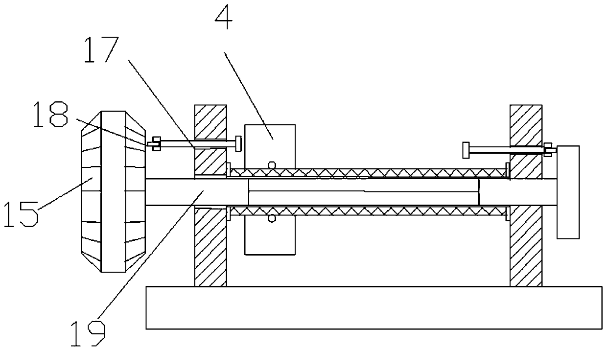
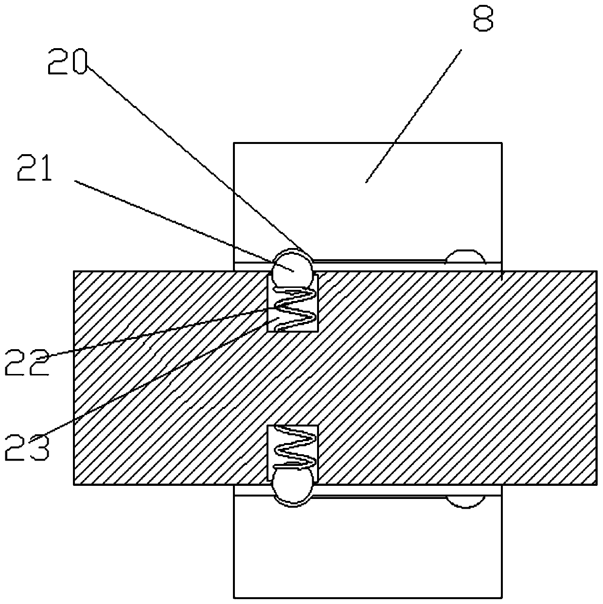
[0028] see image 3 , on the basis of Embodiment 1, the side wall of the sliding rod 17 is provided with a nesting groove 23, and the inside of the nesting groove 23 is slidingly nested with a ball 21, and the ball 21 can slide inside the nesting groove 23, and the nesting groove 23 is a cylindrical structure with a convex cross-section, thereby preventing the ball 21 from slipping out of the nesting groove 23. A spring 22 is placed inside the ball 21 inside the nesting groove 23, and the spring 22 makes the ball 21 slide outwards. The support frame 8 and There are two sets of grooves 20 inside the support seat, and the balls 21 are nested inside the 2, and the sliding rod 17 is subjected to the jacking force, so that the balls 21 are converted and slid inside the two grooves 20, thus avoiding the free movement of the rotating rod 19. The stability of the meshing of the driven gear 15 with the external driving gear 13 and the transmission gear 14 is ensured.


PUM


Abstract

The invention relates to the technical field of cable processing, and particularly discloses an energy-saving electronic cable winding device. The energy-saving electronic cable winding device comprises a base and a cable roller, wherein a supporting frame and a supporting seat are fixedly arranged on the upper surface of the base; a motor is fixedly arranged on the side wall of one end of the supporting frame; an output shaft of the motor is coaxially and fixedly connected with a driving belt wheel and a rotating shaft; an inner driving gear, a driven belt wheel and an outer driving gear which are coaxially and fixedly connected are rotationally arranged on the side wall of the other end of the supporting frame; a transmission gear and a driven gear are arranged on the supporting frame; the driven gear is coaxially connected with a rotating rod; a threaded groove rod is rotationally arranged between the supporting frame and the supporting seat; the rotating rod is nested in the threaded groove rod in a sliding mode; a sliding block is nested on the threaded groove rod; a rotating roller is arranged on the sliding block; and sliding rods are nested on the two sides of the sliding block on the supporting frame and the supporting seat in a sliding mode. The energy-saving electronic cable winding device has the advantages of being simple in structure, convenient to operate, low inmanufacturing cost, good in regularity, smooth in sliding, good in stability and convenient to popularize and implement.

Description

technical field [0001] The invention relates to the technical field of cable processing, in particular to an energy-saving electronic cable winding device. Background technique [0002] Electronic cables are also called cables, and cables are often used in winding devices in production and use. The cable winding machine divides the cables on the I-shaped wheel into small bundles of cables. At present, the cable winding machines on the market include a control box, and one side of the control box is connected to a winding drum. There is a lead part on the top, the lead part is connected with the control box, there are baffles at both ends of the reel, the baffle includes a left baffle and a right baffle, and the right baffle is fixedly connected to the reel when the cable winding machine is working , when the wire reel is to be taken down, the right baffle is separated from the reel, so that the wire reel can be taken out from the right side. Usually the wire is tightly wou...

Claims


Application Information

Patent Timeline
Patent Type & Authority Applications(China)
IPC IPC(8): B65H54/28B65H54/44B65H54/70
CPCB65H54/2818B65H54/44B65H54/70B65H2701/34
Inventor 袁敏
Owner GUANYUN POWER SUPPLY OF JIANGSU ELECTRIC POWER
Why Eureka
Try Eureka