Lens unit and image sensing apparatus incorporated with the same

a technology of image sensing apparatus and lens unit, which is applied in the direction of mountings, optics, instruments, etc., can solve the problems of defocus, reduced commercial value of lens unit, and increased backlash resulting from zoom operation, so as to prevent the free movement of cam cylinder and simplify the arrangement

Inactive Publication Date: 2010-08-26
KONICA MINOLTA OPTO
View PDF3 Cites 6 Cited by
  • Summary
  • Abstract
  • Description
  • Claims
  • Application Information

AI Technical Summary

Benefits of technology

[0012]In view of the above, it is an object of the present invention to provide a lens unit capable of preventing free movement of a cam cylinder with a simplified arrangement, and an image sensing apparatus incorporated with the lens unit.
[0014]The lens unit having the above arrangement, and the image sensing apparatus incorporated with the lens unit enable to prevent free movement of the cam cylinder with a simplified arrangement.

Problems solved by technology

As a result, backlash resulting from a zoom operation is increased.
When the driving mechanism is freely moved, a smooth driving operation for a zoom operation is obstructed, which may lower the commercial value of the lens unit.
In a fixed mode where the focal position is fixed, the focal position may be displaced, or a measurement error may be included in distance information for auto-focus control, with the result that a defocus may occur.
The drawback becomes conspicuous by an increase in the lens weight, the pressure angle, or a backlash amount resulting from a zoom operation.
The technique, however, may increase a load necessary for driving the cam cylinder, and generate dusts resulting from abrasion of the cam cylinder.
The technique, however, has a drawback that the suede cloth is flattened, and is likely to wear over time.
In the methods, however, there is a likelihood that a cam cylinder may be freely moved by a spring force of the coil spring, depending on an arrangement of an optical system.
Thus, the methods may be impractical in the case where a change in position between lens groups is relatively large, and obstruct miniaturization.
Accordingly, the length of the cam cylinder is unavoidably increased, which not only obstructs miniaturization, but also increases the difficulty in assembling the lens unit.
Thus, the method is not desirable in the aspect of productivity.

Method used


Image

  • Lens unit and image sensing apparatus incorporated with the same
  • Lens unit and image sensing apparatus incorporated with the same
  • Lens unit and image sensing apparatus incorporated with the same

Examples


Embodiment Construction

[0027]In the following, an embodiment of the invention is described referring to the drawings. Elements with like reference numerals throughout the drawings have like arrangements, and repeated description thereof is omitted, as necessary.

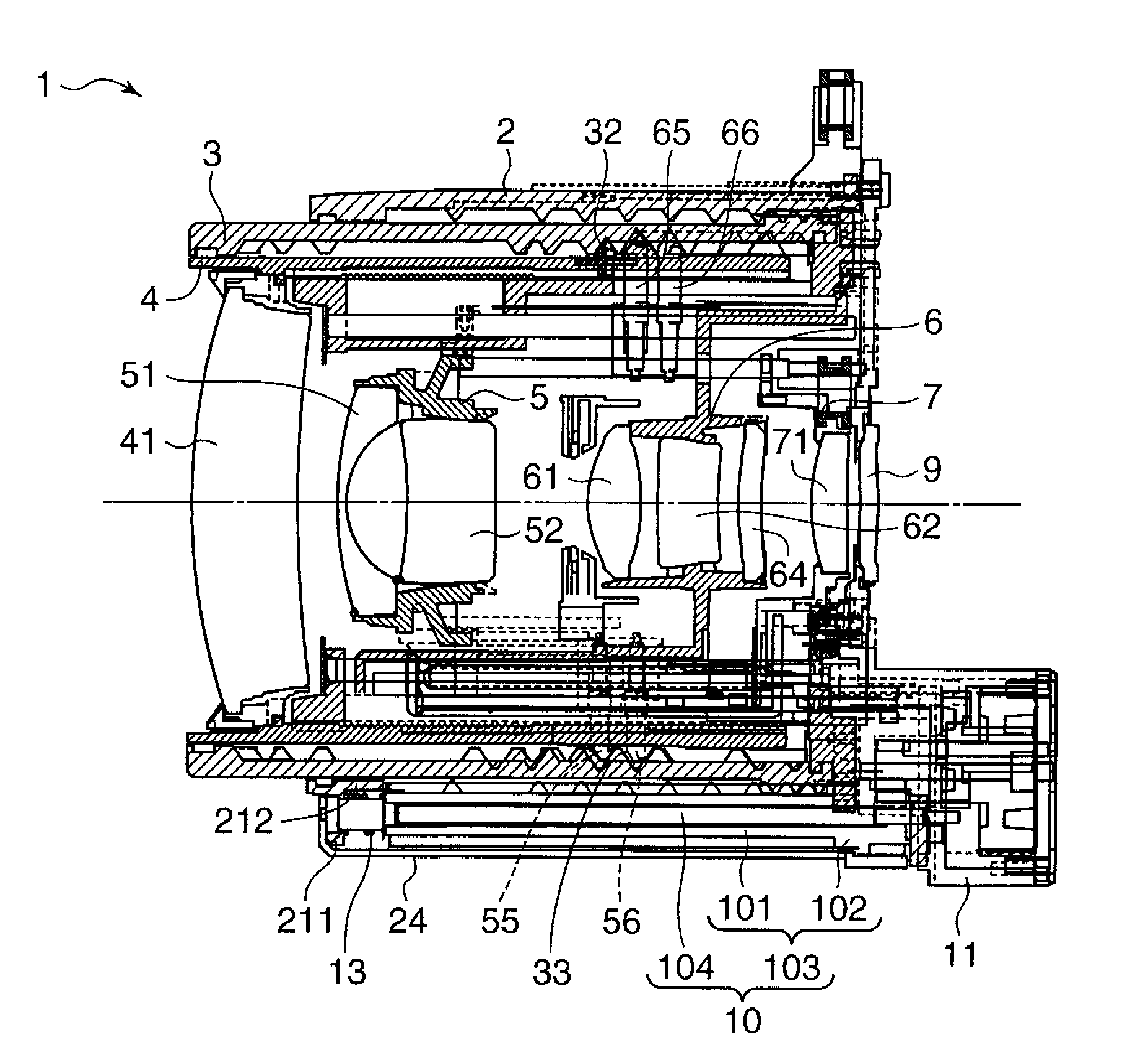
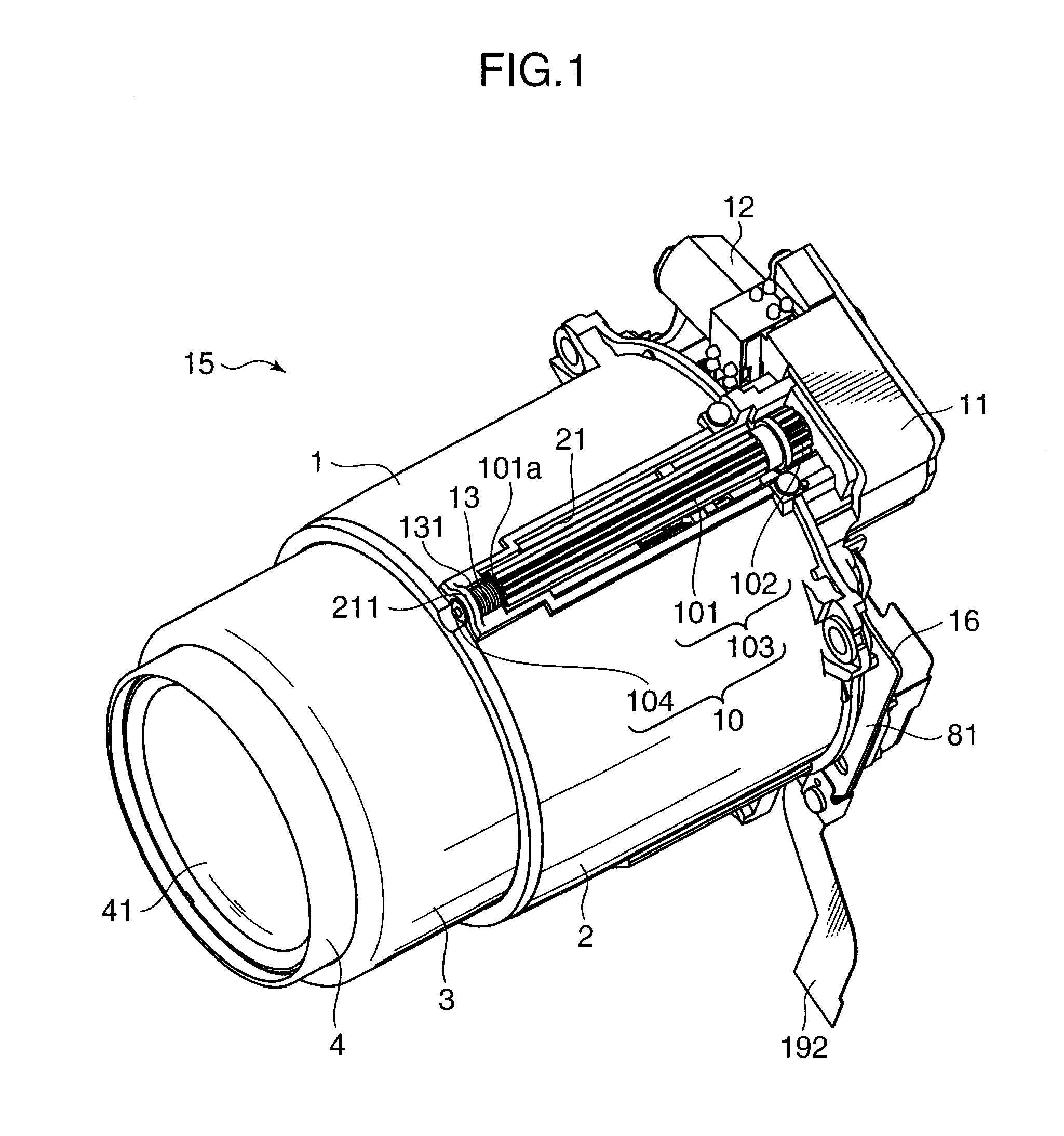
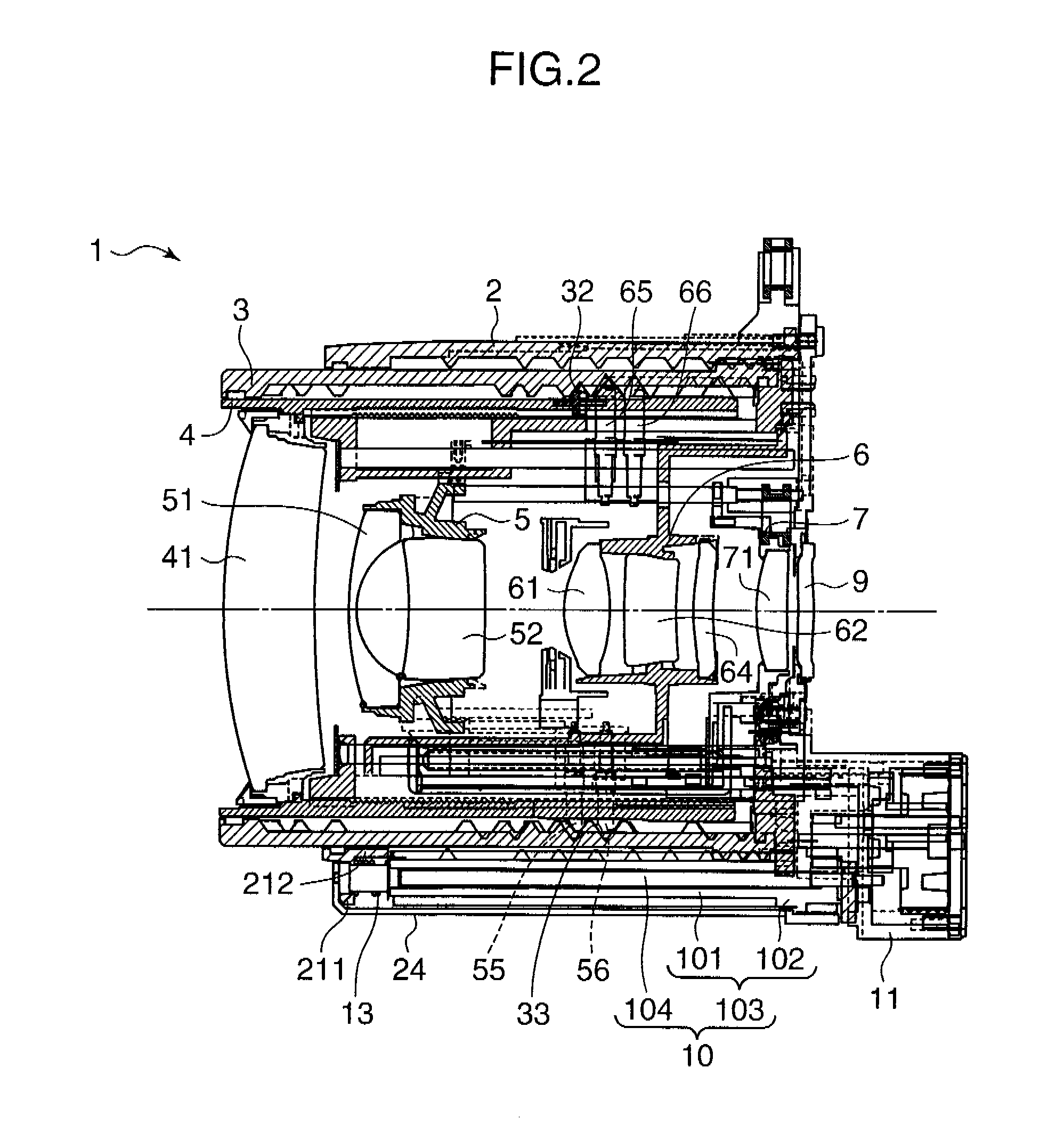
[0028]FIG. 1 is a perspective view showing an overall arrangement of an image sensing apparatus incorporated with a lens unit embodying the invention. FIGS. 2 through 4 are elevational sectional views of the lens unit shown in FIG. 1. The lens unit 1 is used in an image sensing apparatus incapable of exchanging a lens unit, and is a lens unit having a high zoom magnification and incorporated with an expandable and contractible lens barrel. FIG. 2 shows a state that the lens barrel is in a retracted state, in other words, a non-use state of the image sensing apparatus. FIG. 3 shows a wide-angle end state, wherein the focal length is set to e.g. 26 mm in terms of 35 mm film. FIG. 4 shows a telephoto end state, wherein the focal length is set to e.g. ...


PUM


Abstract

In a lens unit 1, and an image sensing apparatus 15 incorporated with the lens unit 1 of the invention, a fixed cylinder 2 is formed with an oblong hole 21 extending in an optical axis direction in a lateral surface of the fixed cylinder 2. A driving force from a driving member such as a motor 12 is transmitted to a gear portion formed on an outer periphery of a cam cylinder 3 by a major axis gear 10 received in the oblong hole 21. Thereby, the cam cylinder 3 is rotated, and a lens holding frame is driven in the optical axis direction for a zoom operation. A pressing member 13 for pressing the major axis gear 10 in the optical axis direction during the zoom operation is provided at an end surface of the major axis gear 10.

Description

[0001]This application is based on Japanese Patent Application No. 2009-040736 filed on Feb. 24, 2009, the contents of which are hereby incorporated by reference.BACKGROUND OF THE INVENTION AND RELATED ART STATEMENT[0002]1. Field of the Invention[0003]The present invention relates to a lens unit and an image sensing apparatus incorporated with the lens unit, and more particularly to a lens unit for use in a single-eye camera incapable of exchanging a lens unit.[0004]2. Description of the Related Art[0005]The single-eye camera is generally provided with a high-magnification zoom lens unit capable of zooming in a wide range from a wide-angle end to a telephoto end, in view of a point that the single-eye camera is incapable of exchanging a lens unit. In order to realize a high zoom magnification, and reduce the lens barrel length in a retracted state for miniaturization, the lens barrel has plural step portions, and the moving amount of a lens group i.e. the protruding amount of a lens...

Claims


Application Information

Patent Timeline
Patent Type & Authority Applications(United States)
IPC IPC(8): G02B7/10
CPCG02B7/102
Inventor MATSUMOTO, TOMOHIROMITANI, YOSHIFUMITSUJIMOTO, YUTAKA
Owner KONICA MINOLTA OPTO
Why Eureka
Try Eureka