

Conductive path
a conductive path and path technology, applied in the direction of coupling contact members, coupling device connections, coupling protective earth/shielding arrangements, etc., can solve the problem of too many parts, and achieve the effect of preventing wear or damag
- Summary
- Abstract
- Description
- Claims
- Application Information
AI Technical Summary
Benefits of technology
Problems solved by technology
Method used
Image

Examples
first embodiment
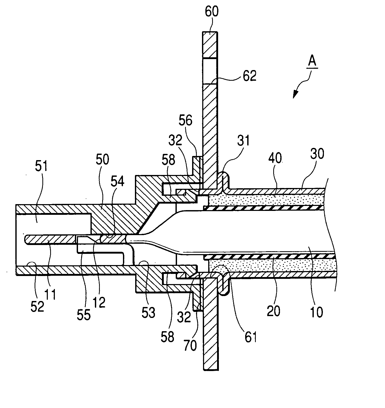
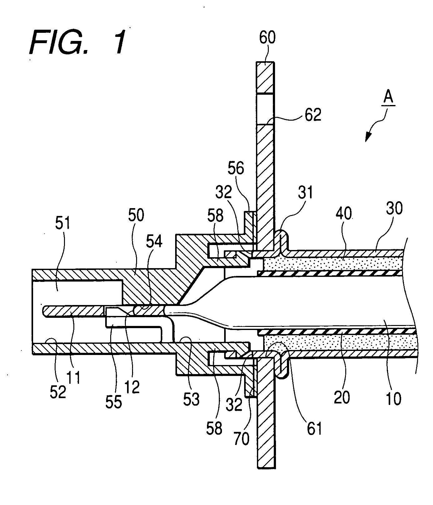
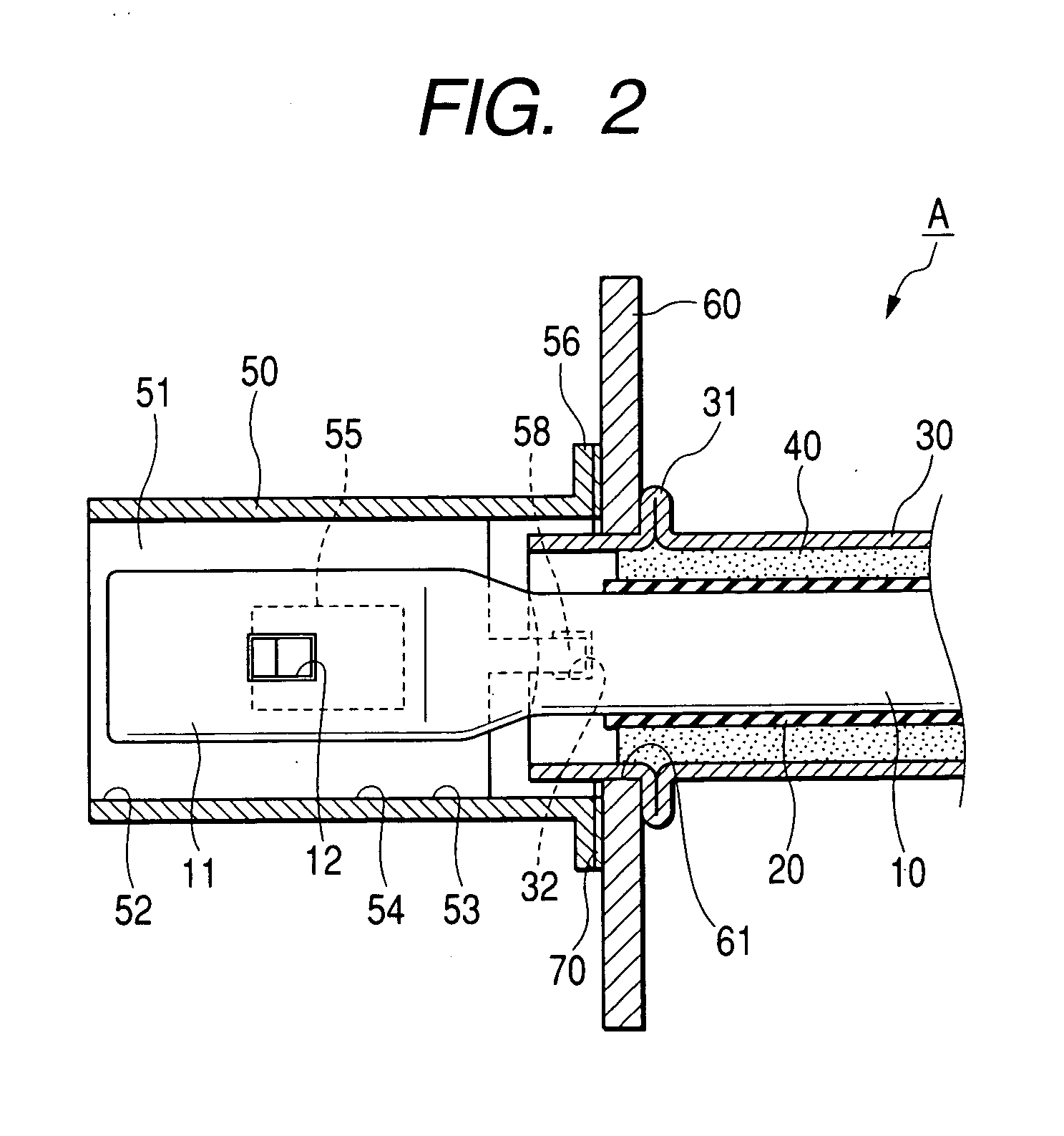
[0027] Hereunder, a first embodiment materialized according to the present invention will be described referring to the accompanying drawings FIG. 1 through FIG. 6.
[0028] A conductive path A according to this embodiment is designed for connection to a apparatus-side connector 80 (an object to be connected) provided in an apparatus B (for example, a motor or an inverter of an electric vehicle).
[0029] The apparatus-side connector 80 is provided with an apparatus-side terminal 81 (a mating terminal), an apparatus-side housing 82 (a mating fitting member) and an apparatus-side shielding shell 83 (a mating shielding member). The apparatus-side shielding shell 83, which constitutes a part of a casing enclosing a main body (not shown) of the apparatus, includes a chamber 84 recessed inwardly (to the left in FIG. 3) from a lateral face thereof. The chamber 84 has a connection hole 85 formed in a back and forth direction through a rear wall thereof, and the apparatus-side housing 82 is fix...
PUM
 Abstract
Description
Claims
Application Information