Communication method and device
A technology of communication equipment and communication methods, applied in the field of communication, can solve the problems of cumbersome and inefficient 5G network procedures, and achieve the effect of improving data migration efficiency and simplifying migration operations
Active Publication Date: 2021-02-02
HUAWEI TECH CO LTD
5 Cites 0 Cited by
AI-Extracted Technical Summary
Problems solved by technology
As a result, the procedures for 4G/5G fusion users to re...
Abstract
A communication method and device, in which a first device determines, according to a received network registration request, that a 4G/5G converged user requests to register a 5G network for the firsttime, and can send first information to a BOSS capable of communicating with a 4G network and a device of the 5G network, so that the BOSS can control the first device according to the first information, and the first device is based on the control of the BOSS. And user data of the 4G/5G converged user in a 4G network is obtained and stored, the 4G/5G converged user being a 4G user using a terminal supporting 5G communication capability. By means of the method, online migration of the user data of the 4G/5G fusion user can be achieved, manual operation is avoided, and therefore migration efficiency is improved.
Application Domain
Network data management
Technology Topic
Engineering5G +5
Image
Examples
- Experimental program(1)
Example Embodiment
[0046]In order to make the objectives, technical solutions, and advantages of the embodiments of the present application clearer, the embodiments of the present application will be described in further detail below with reference to the accompanying drawings. The specific method in the method embodiment can also be applied to the device embodiment or the system embodiment. Among them, in the description of the present application, unless otherwise specified, "plurality" means two or more.
[0047]Before introducing this application, firstly, some terms in the embodiments of this application and the compatible architecture of the 5G network and the 4G network will be briefly explained to facilitate the understanding of those skilled in the art.
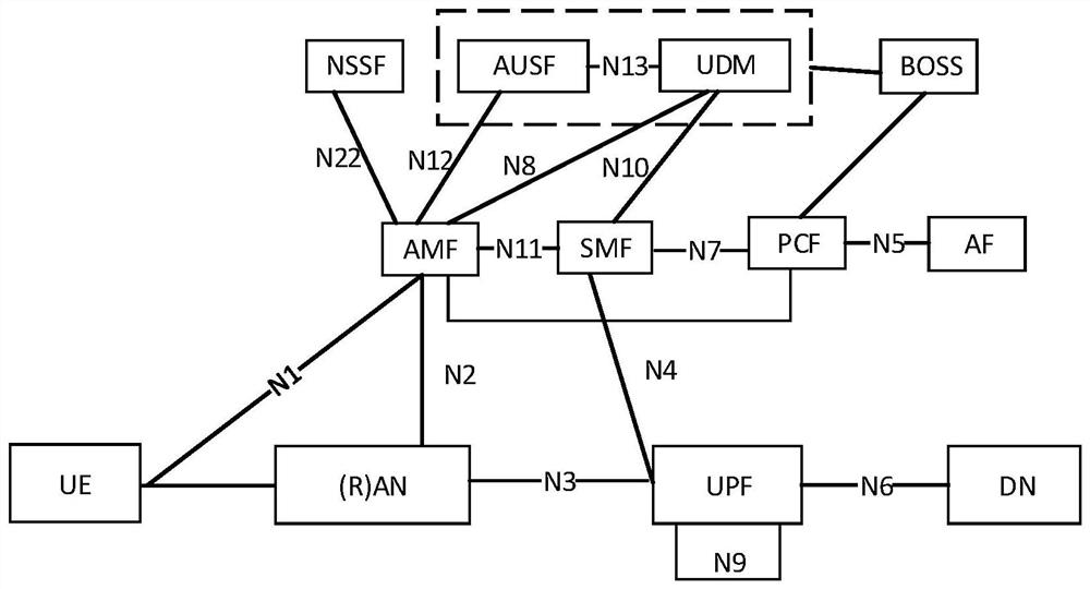
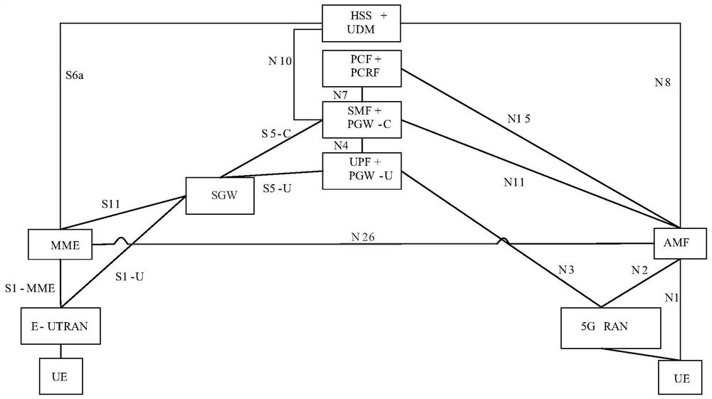
[0048]1) Please refer tofigure 1 , Which is a compatible architecture of the 5G network and the 4G network, may be a specific application scenario of the embodiment of the present application.figure 1 The shown network architecture may include three parts, namely a terminal equipment part, a data network (DN) part, and an operator network part.
[0049]Among them, the operator's network can include policy control function (PCF) network elements, unified data management (UDM) network elements, application function (AF) network elements, access and mobility management Function (access and mobility management function, AMF) network element, session management function (session management function, SMF) network element, (radio) access network ((radio) access network, (R) AN), and user plane function (user plane) function (UPF) network element, authentication server function (authentication server function, AUSF) network element, network slice selection function (network slice selection function, NSSF) network element, etc. In the above-mentioned operator network, parts other than the (wireless) access network part may be referred to as the core network part. For the convenience of description, the following takes (R)AN called RAN as an example for description.
[0050]The above-mentioned network architecture may also include a business and operation support system (BOSS), which provides an end-to-end operation process for the operator’s operation support platform to support the operator’s processing such as customer service, rating, billing, and settlement. And daily affairs such as expediting.
[0051]The terminal equipment (also referred to as user equipment (UE)) of the present application is a device with a wireless transceiver function, which can be deployed on land, including indoor or outdoor, handheld or vehicle-mounted; or on water (Such as ships, etc.); it can also be deployed in the air (such as airplanes, balloons, satellites, etc.). The terminal device may be a mobile phone, a tablet computer (pad), a computer with a wireless transceiver function, a virtual reality (VR) terminal, an augmented reality (AR) terminal, an industrial control (industrial control) Wireless terminals in ), wireless terminals in self driving, wireless terminals in remote medical, wireless terminals in smart grid, and wireless terminals in transportation safety , Wireless terminals in smart cities, wireless terminals in smart homes, etc.
[0052]The above-mentioned terminal equipment can establish a connection with the operator's network through an interface (such as N1, etc.) provided by the operator's network, and use services such as data and/or voice provided by the operator's network. The terminal device can also access the DN through the operator's network, and use the operator's service deployed on the DN and/or the service provided by a third party. Among them, the aforementioned third party may be a service party other than the operator's network and terminal equipment, and may provide other services such as data and/or voice for the terminal equipment. Among them, the specific form of expression of the above-mentioned third party can be determined according to actual application scenarios, and is not limited here.
[0053]RAN corresponds to different access networks, such as 4G networks, 5G networks, wired access, wireless base station access, and other methods. The corresponding access network device is a device that provides wireless communication functions for the terminal. The access network equipment includes, but is not limited to: next-generation base stations (g nodeB, gNB), evolved node B (evolved node B, eNB), radio network controller (RNC), and node B ( node B, NB), base station controller (BSC), base transceiver station (BTS), home base station (for example, homeevolved nodeB, or home node B, HNB), baseband unit (BBU) ), transmission point (transmitting and receiving point, TRP), transmission point (transmitting point, TP), mobile switching center, etc. In this application, the RAN may be a network composed of multiple RAN nodes, which implements wireless physical layer functions, resource scheduling and wireless resource management, wireless access control, and mobility management functions. For example, 5G RAN is connected to UPF network elements through user plane interface N3 to transmit UE data; RAN uses control plane interface N2 to connect to core network access and AMF network elements to establish control plane signaling connections for wireless access Bearer control and other functions.
[0054]In this application, the mobility management network element is the control plane network element provided by the operator network, and is responsible for the access control and mobility management of terminal equipment accessing the operator’s network, including, for example, mobility status management and the allocation of temporary user identities. Functions such as authentication and authorization of users. In 5G, the mobility management network element can be an AMF network element. In future communications such as the 6th generation (6G), the mobility management network element can still be an AMF network element or have other names. The application is not limited. The AMF network element is mainly responsible for UE authentication, UE mobility management, network slicing selection, session management function (Session Management Function, SMF) network element selection and other functions; as the anchor point for the N1 and N2 signaling connection, and is the SMF network The element provides routing of N1 and N2 Session Management (Session Management, SM) messages; maintains and manages the status information of the UE.
[0055]In this application, the session management function network element SMF may be a control plane network element provided by an operator network, and is responsible for managing a protocol data unit (protocol data unit, PDU) session of a terminal device. A PDU session is a channel used to transmit PDUs, and terminal devices need to transmit PDUs to each other through the PDU session and the DN. The PDU session is established, maintained, and deleted by the SMF network element. SMF network elements include session management (such as session establishment, modification and release, including tunnel maintenance between UPF and RAN), UPF network element selection and control, service and session continuity (Service and Session Continuity, SSC) mode selection, Session-related functions such as roaming. SMF network elements and AMF network elements are connected through the N11 interface, and are mainly responsible for all control plane functions of UE session management, including UPF network element selection, Internet Protocol (IP) address allocation, and session Quality of Service (QoS) ) Attribute management, obtaining policy control and charging (Policy Control and Charging, PCC) rules from PCF network elements. In 5G, the session management network element may be an SMF network element. In future communications such as 6G, the session management network element may still be an SMF network element or have other names, which is not limited in this application.
[0056]In this application, the user plane network element is a gateway provided by an operator, and a gateway for communication between the operator's network and the DN. UPF network elements include user plane-related functions such as data packet routing and transmission, packet inspection, service usage reporting, Quality of Service (QoS) processing, lawful monitoring, uplink packet inspection, and downlink packet storage. In 5G, the user plane network element can be a UPF network element, which is connected to the SMF network element through the N4 interface. The UPF network element serves as the anchor point of the PDU session connection, and is responsible for the data packet filtering, data transmission or forwarding, and rate control of the UE. , Generate billing information, etc. In future communications such as 6G, the user plane network element may still be a UPF network element or have other names, which is not limited by this application.
[0057]DN, also called packet data network (PDN), is a network located outside the operator’s network. The operator’s network can be connected to multiple DNs. Multiple services can be deployed on the DN. It communicates with UPF through the N6 interface. Network element connection can provide data and/or voice services for terminal equipment. For example, DN is the private network of a smart factory. The sensors installed in the workshop of the smart factory can be terminal devices. The control server of the sensor is deployed in the DN, and the control server can provide services for the sensors. The sensor can communicate with the control server, obtain instructions from the control server, and transmit the collected sensor data to the control server according to the instructions. For another example, the DN is the internal office network of a company. The mobile phones or computers of employees of the company can be terminal devices, and the mobile phones or computers of employees can access information and data resources on the company's internal office network.
[0058]In this application, the data management network element is a control plane network element provided by the operator, and is responsible for storing the subscriber permanent identifier (SUPI), credential, and security context of the subscribers in the operator’s network. context), contract data and other information. The information stored in UDM network elements can be used for authentication and authorization of terminal equipment accessing the operator's network. Among them, the contracted users of the above-mentioned operator's network may specifically be users who use the services provided by the operator's network, such as users who use China Telecom's mobile phone core card, or users who use China Mobile's mobile phone core card. The permanent subscription identifier (SubscriptionPermanent Identifier, SUPI) of the aforementioned subscriber may be the number of the mobile phone core card, etc. The credential and security context of the aforementioned subscriber may be a small file stored such as the encryption key of the mobile phone core card or information related to the encryption of the mobile phone core card for authentication and/or authorization. The aforementioned security context may be data (cookie) or token (token) stored on the user's local terminal (for example, mobile phone). The contract data of the aforementioned subscriber may be the supporting service of the mobile phone core card, such as the data package of the mobile phone core card or the network usage. It should be noted that permanent identifiers, credentials, security contexts, authentication data (cookies), and tokens are equivalent to information related to authentication and authorization. In this application, no distinction or restriction is made for the convenience of description. If no special instructions are given, the embodiments of the present application will be described using a security context as an example, but the embodiments of the present application are also applicable to authentication and/or authorization information in other expression modes. In 5G, the data management network element can be a UDM network element, which is connected to the AMF network element through the N8 interface, and is connected to the SMF network element through the N10 interface. It is used to store user-related subscription information, and is used for these through the N8 and N10 interfaces. The corresponding network element provides contract-related parameter information. In future communications such as 6G, the data management network element may still be a UDM network element or have other names, which is not limited by this application.
[0059]In this application, the policy control network element is a control plane function provided by the operator, and is used to provide a PDU session policy to the SMF network element. Policies can include charging-related policies, QoS-related policies, and authorization-related policies. In 5G, the policy control network element can be a PCF network element, which is connected to the SMF network element through the N7 interface, and is connected to the AMF network element through the N15 interface, which is used to generate and store the PCC rules related to session management and provide them to the SMF network element. It is also used to generate strategy information related to mobility management and provide it to AMF network elements. In this architecture, the PCF connected to the AMF and the SMF respectively correspond to the access and mobility control policy control function (PCF for access and mobility control, AM PCF) and the session management policy control function (PCF for session management, SM PCF). The deployment scenario may not be the same PCF entity. In future communications such as 6G, the policy control network element may still be a PCF network element or have other names, which is not limited by this application.
[0060]In this application, the network open network element is the control plane network element provided by the operator, for example, the AF network element: connects to the PCF network element through the N5 interface, and mainly conveys the requirements of the application side to the network side, such as QoS requirements. The AF network element can be a third-party functional entity or an application service deployed by an operator, such as an IP multimedia subsystem (IP multimedia subsystem, IMS) voice call service.
[0061]In this application, the authentication service network element is the control plane network element provided by the operator, for example, the AUSF network element: connects to the UDM network element through the N13 interface, and connects to the AMF network element through the N12 interface, mainly 3GPP and non-3GPP access Provide authentication function.
[0062]In this application, the network division network element is the control plane network element provided by the operator, for example, the NSSF network element: connects to the AMF network element through the interface N22, and provides the network slice selection function for the access user.
[0063]figure 1 Among them, N1, N2, N3, N4, N5, N6, N7, N8, N10, N11, N12, N13, and N22 are the interface serial numbers. The meaning of these interface serial numbers can refer to the meaning defined in the 3GPP standard protocol, which is not limited here.
[0064]In suchfigure 1 In the architecture shown, UDM network elements suitable for 5G and AUSF network elements suitable for 4G are co-located (e.g.figure 1 Shown by the dashed box). BOSS can perform data interaction with UDM network elements and PCF network elements, so as to realize the control of 4G network and 5G network.
[0065]In addition, in order to achieve a smooth transition from 4G network to 5G network, the standard also proposes an architecture for the integrated deployment of 4G core network and 5G core network, please refer tofigure 2 , Is a 5G network and evolved packet core (evolved packet core, EPC)/evolved universal terrestrial radio access network (evolved universal terrestrial radio access network, E-UTRAN) converged architecture, which is one of the embodiments of this application Specific application scenarios. same,figure 2 The shown network architecture may also include three parts, namely the terminal equipment part, the DN part and the operator network part. versusfigure 1 The difference is,figure 2 The operator’s network part includes both the 4G operator’s network and the 5G operator’s part.figure 2 Middle andfigure 1 Different network elements, andfigure 1 The functions of the repeated network elements shown are not repeated here:
[0066]Among them, the serving gateway (SGW): connects to the UPF network element through the S5-U interface, and connects to the SMF network element through the S5-U interface, and is used for the control of the mobility management entity (MME) network element The routing and forwarding of data packets are carried out.
[0067]A packet data network-gateway (PGW) includes a control plane packet data gateway (PGW-C) and a user plane packet data gateway (packet data network gateway-user, PGW-U). The PGW-C in the 4G network is co-located with the SMF in the 5G network, connected to the AMF network element through the N11 interface, and is mainly responsible for all control plane functions of UE session management. The PGW-U is co-located with the UPF in the 5G network, connected to the RAN through the N3 interface, and is mainly responsible for all user plane functions of UE session management. The UDM in the 5G network is co-located with the HSS in the 4G network to manage user user data, etc.
[0068]MME network element: connect with UDM network element through S6a interface, connect with SGW through S11 interface, and connect with E-UTRAN through S1-MME interface. Mainly responsible for functions such as mobility management, bearer management, user authentication, SGW and PGW selection. Among them, under the single registration from the 5G network to the 4G network, the switching of the N26 interface is supported between the MME network element and the AMF network element. Of course, the switching of other interfaces can also be supported between the MME network element and the AMF network element, which is not limited here.
[0069]E-UTRAN: Connect to SGW through S1-U interface, and connect to MME through S1-MME interface. Among them, the S1-MME interface is the reference point of the control plane protocol between E-UTRAN and the MME; the S1-U interface is the reference point of the user plane tunnel for each bearer between the E-UTRAN and the SGW.
[0070]It should be understood that infigure 2 Each network element shown in the figure may be independent, or two or more network elements may be integrated, which is not specifically limited in the embodiment of the present application.
[0071]In addition, for the evolution and deployment of 5G networks, the current 3GPP standard also defines a non-standalone (NSA) architecture. Please refer toimage 3 (a)-3(b),image 3 (a) is a schematic diagram of an independent networking (stand alone, SA) architecture,image 3 (b) is a schematic diagram of the NSA architecture. Compared with the SA defined by the SA, the UE is directly connected to the 5G core network through the S1-U interface between the 5G base station and the 5G core network. In the NSA networking mode, the UE mainly accesses the EPC network through E-UTRAN and is deployed in the 5G base station In the area, E-UTRAN can decide whether to insert a 5G NR branch to enjoy the large bandwidth and low delay services supported by 5G base stations. inimage 3 In the architecture shown in (b), the core network part is still the EPC network, but at the same time there may be two user plane paths for the UE, corresponding to one signaling path. The technical solutions provided in the embodiments of the present application may be applicable to SA and NSA as well.
[0072]For the convenience of description, in this application, the AMF network element is referred to as AMF, UDM network element is referred to as UDM, RAN device is referred to as RAN, and terminal equipment is referred to as UE.
[0073]Understandably, the abovefigure 1 withfigure 2 The network elements or functions in can be network elements in hardware devices, software functions running on dedicated hardware, or virtualization functions instantiated on a platform (for example, a cloud platform). Optionally, the foregoing network element or function may be implemented by one device, or jointly implemented by multiple devices, or may be a functional module in one device, which is not specifically limited in the embodiment of the present application.
[0074]Some English abbreviations in this article are the description of the embodiments of the present application taking 4G networks and current 5G networks as examples, which may change with the evolution of the network, and the specific evolution can refer to the description in the corresponding standard.
[0075]When a 4G user purchases a terminal with 5G capabilities, he can become a 4G/5G converged user, that is, a 5G terminal can be used for 4G services or 5G services. At present, after purchasing a 5G terminal, a user usually needs to register for a 5G network at the operator’s business hall to become a 4G/5G converged user. When the operator’s staff registers the user on the 5G network, they need to manually register the user on the 4G network. After the user data in the network is migrated from the HSS to the UDM network element in the 5G network, the 4G/5G converged users can use the services provided by the 5G network normally. As a result, 4G/5G converged users have cumbersome procedures and low efficiency when registering on 5G networks.
[0076]To solve the above technical problems, based onfigure 2 The architecture shown, such asFigure 4 As shown, this application provides a communication method. The method is applied to communication systems of two different standards, for example, in an architecture including a 5G network and a 4G network. In this method, when a 4G/5G converged user performs 5G services, the user data of the 4G/5G converged user can be triggered by BOSS to migrate to a unified data repository (UDR) network element, and the UDR network element is mainly responsible for user data For example, it is responsible for the access function of contract data, policy data, application data and other data. UDM network elements (PCF network elements) can directly obtain user data from UDR network elements, that is, support online migration of 4G/5G converged users User data, which does not require the manual participation of the operator’s business hall, can simplify the migration operation of user data from the 4G network to the 5G network.
[0077]In addition, when 4G/5G converged users perform 5G services, the migration of user data of 4G/5G converged users is triggered, so there is no need to migrate all user data using 5G terminals from HSS to UDM network elements in advance. UDM needs to be deployed There are fewer network elements, thereby reducing the cost of building 5G.
[0078]Of course, the two different communication systems to which this method is applied can also be 5G networks and other communication systems, such as wireless fidelity (wifi), worldwide interoperability for microwave access (WiMAX), global mobile communications (global system of mobile communication, GSM) system, code division multiple access (CDMA) system, wideband code division multiple access (WCDMA) system, general packet radio service (general packet radioservice, GPRS) ), long term evolution (LTE) system, advanced long term evolution (LTE-A) system, universal mobile telecommunication system (UMTS), and the 3rd generation partnership program (the 3rd generation partnership project, 3GPP) related cellular systems, etc. In the following, the application of this method to a communication system including 4G networks and 5G networks is taken as an example.
[0079]In addition, the solution of this application can also be applied to future-oriented communication technologies. The system described in the embodiment of this application is to illustrate the technical solution of the embodiment of this application more clearly, and does not constitute a comparison of the technical solution provided by the embodiment of this application. As a limitation, those of ordinary skill in the art know that with the evolution of the network architecture, the technical solutions provided in the embodiments of the present application are equally applicable to similar technical problems.
[0080]Specifically, please refer toFigure 4 The embodiment of the present application provides a communication method, which includes the following steps:
[0081]Step S401: The first device determines that the 4G/5G converged user requests to register on the 5G network for the first time.
[0082]Among them, 4G/5G converged users are 4G users who use UEs that support 5G communication capabilities. The first device is a device used to save user data in the 5G network, for example, it can befigure 2 UDM or PCF is shown, where UDM is used to store subscription data in user data, and PCF is used to store policy data in user data, such as charging policy data.
[0083]When a 4G user purchases a 5G capable UE, 5G services can be activated, that is, a 4G user performs 5G services through the UE, and the UE needs to access the 5G network. The process of whether the UE accesses the 4G network or the 5G network can follow the access process of the prior art, which will not be described here.
[0084]When the UE accesses the 5G network in the coverage area of the 5G network, the UE can go online to the 5G network elements, such as UDM or PCF, through AMF. If UDM or PCF determines that there is no user data of the 4G/5G converged user using the UE, such as subscription data or policy data, and the 4G/5G converged user is a legitimate user, such as a user registered in the 4G network , UDM or PCF can determine that the 4G/5G converged user requests to register on the 5G network for the first time, that is, the network element in the 5G network does not save the user data of the 4G/5G converged user. Since the user data of the 4G/5G converged user has been registered in the 4G network before, the 4G network stores the user data of the 4G/5G converged user. Therefore, in this application, UDM or PCF can obtain the user data of the 4G/5G converged user from the 4G network, and save the obtained user data of the 4G/5G converged user, thereby migrating the 4G/5G converged user’s data online. User data, avoid manual participation and improve migration efficiency.
[0085]Step S402: The first device sends first information to the BOSS, so that the BOSS receives the first information.
[0086]If the first device determines that the 4G/5G converged user requests to register on the 5G network for the first time, the first device may send the first information to the BOSS, where the BOSS can communicate with devices on the 4G network and the 5G network. The first information can be used to inform the BOSS to migrate the user data of the 4G/5G converged user in the 4G network from the 4G network to the 5G network.
[0087]If the first device is UDM or PCF, and since there is no service interface between BOSS and UDM or PCF, in this application, the first device can use UDR as the service interface between UDM or PCF and BOSS, that is, UDM or The PCF sends the first information to the BOSS through a user data repository (UDR) that can communicate with the UDM. In this case, when the UDM or PCF determines that the 4G/5G converged user requests to register on the 5G network for the first time, it can inform the UDR that the 4G/5G converged user requests to register on the 5G network for the first time. At this time, the UDR sends the first information to the BOSS.
[0088]Of course, the above-mentioned first device can also be understood as a UDR. In this case, the UDM or PCF informs the UDR that the 4G/5G converged user requests to register on the 5G network for the first time. For example, the UDM or PCF can send instruction information to the UDR. The instruction information can be used to indicate that the user data of the 4G/5G converged user does not exist in the 5G network, and the 4G/5G converged user is a legitimate user, so the UDR follows the instructions The information can confirm that a 4G/5G converged user requests to register for a 5G network for the first time.
[0089]Step S403: After receiving the first information, the BOSS can control the first device to obtain the user data of the 4G/5G converged user from the 4G network, so that the first device obtains and stores the user data of the 4G/5G converged user from the 4G network; Correspondingly, the first device acquires and stores the user data of the 4G/5G converged user in the 4G network based on the control of the BOSS.
[0090]In order to facilitate understanding, the following combined with specific scenarios and examples, the aboveFigure 4 The illustrated embodiment is described in detail.
[0091]Scenario 1: Take the user data of 4G/5G converged users including subscription data as an example.
[0092]Such asFigure 5 As shown, the architecture diagram of each network element involved in scenario 1 provided by this application.Figure 5 The network architecture shown includes network elements in a 5G network and network elements in a 4G network. For example, the network elements in the 5G network include AMF, SMF, and UDM, where UDM may further include UDR. The network elements in the 4G network include MME or mobile switching center (mobile switching center, MSC), routing agent node (diameter routing agent, DRA) or signaling transfer point (signalling transfer point, STP), and HSS, where HSS includes the front end (front end, FE) and back end (back end, BE). In scenario 1, a 5G capable UE used by a 4G user, that is, a 5G UE can access a 4G network in a 4G network coverage area, and can access a 5G network in a 5G network coverage area.Figure 5 Take access to a 5G network as an example.
[0093]In scene one, such asImage 6 Shown asFigure 4 Shown is a specific implementation process of the embodiment, including the following steps:
[0094]Step S601: The 5G UE sends an attach message to the AMF, so that the AMF receives the attach message.
[0095]Wherein, the attach message can be considered as a network access request message. Such asFigure 5 As shown, in step ①, if the UE accesses in the area covered by the 5G network, it can go online to UDM through AMF, or it is a device jointly established by UDM and AUSF. Here and in the following, the equipment jointly installed by UDM and AUSF is collectively referred to as UDM.
[0096]Step S602: The AMF sends an authentication request to the UDM, so that the UDM receives the authentication request.
[0097]After receiving the authentication request, the UDM authenticates the UE. Specifically, UDM can determine whether the UE is accessed from the 5G network. If it is determined that the UE is accessed from a 5G network, UDM can determine whether the UE is a legal user, that is, whether it has been registered on a non-4G network. If the UE has been registered on a non-4G network, then the UE may be a legal user. After UDM determines that the UE is a legitimate user, it determines whether the registration information of the UE is in the UDM. If the UDM determines that the registration information of the UE is not on the UDM, the UDM determines that the UE is registering on the 5G network for the first time.
[0098]Step S603: The UDM sends the first information to the BOSS, so that the BOSS receives the first information.
[0099]The first information may be used to instruct the BOSS to migrate the 4G/5G converged user's subscription data in the 4G network from the 4G network to the 5G network. When the UDM determines that the UE is registering on the 5G network for the first time, it can send the first message to the BOSS to notify the BOSS to perform 5G user account opening and subscription data migration operations.
[0100]Specifically, UDM sends the first message to BOSS mainly includes two steps, such asFigure 5 As shown, in step ②, first, the UDM sends the first information to the UDR, and then, as in step ③, the UDR forwards the first information to the BOSS. That is, the UDM can send the first information to the BOSS first information through the UDR.
[0101]Step S604: The BOSS sends a response message of the first information to UDM. This step is optional and not essential, so inImage 6 The dotted line is used to indicate.
[0102]Step S605: The BOSS sends a trigger message to the UDM, so that the UDM receives the trigger message.
[0103]UDR is a part of UDM. BOSS sends a trigger message to UDM, which can be considered as BOSS sends a trigger message to UDR. For example, such asFigure 5 In the step ④ shown, BOSS sends a trigger message to UDR. The trigger message may instruct UDR to migrate the 4G/5G converged user's subscription data in the 4G network from the 4G network to the 5G network.
[0104]Exemplarily, the trigger message may refer to the access authority. For example, the trigger message carries authority information of the network element located on the 4G network that the UDR can access. The network element located on the 4G network may, for example, store the user's subscription in the 4G network. The second device for data. For example, HSS.
[0105]Step S606: The UDM sends a request message to the HSS based on the above-mentioned access authority for requesting to obtain the user's subscription data in the 4G network from the HSS.
[0106]UDM sends a request message to the HSS according to the trigger message, so as to realize the purpose of migrating the subscription data of 4G/5G converged users in the 4G network from the 4G network to the 5G network. Specific, such asFigure 5 As shown in step ⑤, UDM can send a request message to the back end (BE) of the HSS to obtain subscription data.
[0107]Step S607: The HSS sends the subscription data of the 4G/5G converged user in the 4G network to the UDM.
[0108]When the UDR receives the trigger message from the BOSS, it can access the second device. For example, the UDR sends a request message to the second device to request to obtain the subscription data of the 4G/5G converged user in the 4G network from the BE. After that, likeFigure 5 As shown, in step ⑤, BE can send the 4G/5G converged user's subscription data in the 4G network to UDR, thereby realizing the migration of the 4G/5G converged user's subscription data in the 4G network from the 4G network to the 5G network .
[0109]Step S608: UDM sends a response message to BOSS.
[0110]In some embodiments, after the UDM receives the subscription data from the BE through the UDR, it may feed back a response message to the BOSS through the UDR, and the response message may be used to indicate whether the UDR has received the subscription data.
[0111]Step S609: After the response message indicates that the UDR has received the subscription data, the BOSS sends a notification message to the UE, so that the UE receives the notification message. Specifically, if the response message indicates that UDR has received subscription data, thenFigure 5 In the step ⑥ shown, the BOSS can also send a notification message to the UE to inform the 4G/5G converged user that the 5G service has been automatically activated.
[0112]It should be noted that the BOSS notifies the 4G/5G converged user that the 5G service has been automatically activated, or before the BOSS triggers UDM, that is, step S609 can be performed before step S605 or step S607, that is, the BOSS first informs the UE, and then performs the subscription data Migration operation.
[0113]Scenario 2: Taking the user data of 4G/5G converged users including subscription data as an example.
[0114]Such asFigure 7 As shown, the architecture diagram of each network element involved in the second scenario provided by this application.Figure 7 The network elements shown in the network architecture andFigure 5 The shown network architecture includes the same network elements. The difference lies in the data exchange process between network elements.
[0115]In scene two, such asFigure 8 Shown asFigure 4 Shown is another specific implementation process of the embodiment, including steps S801-S807. Among them, step S801 is the same as step S601, step S802 is the same as step S602, and step S803 is the same as step S603, which will not be repeated here.
[0116]versusImage 6 The difference in the flow shown is that after receiving the first information, the BOSS can first obtain the contract data, and then send the obtained contract data to the UDM. Specifically, it includes the following steps S804 and S805.
[0117]Step S804: The BOSS sends a request message to the second device, and the request message requests to obtain subscription data in the second device.
[0118]Such asFigure 7 In the step ④ shown, the BOSS can send a request message to the BE in the HSS for requesting to obtain the subscription data of the 4G/5G converged user from the BE.
[0119]Step S805: The HSS sends the subscription data to the BOSS.
[0120]Step S806: The BOSS sends the acquired subscription data to UDM.
[0121]Such asFigure 7 In the step ⑤ shown, the BOSS sends the acquired subscription data to the UDR, and the UDM can obtain the subscription data from the UDR.
[0122]Step S807: UDM sends a response message of receiving subscription data to BOSS.
[0123]Step S808: The BOSS sends a notification message to the UE.
[0124]Step S807 is the same as step S608, and step S808 is the same as step S609, which will not be repeated here.
[0125]The above isFigure 5 withFigure 7 The shown network architecture illustrates the migration process of the user's subscription data. The following takes the migration of the user's policy data as an example to introduce the communication method provided in the embodiment of the present application.
[0126]It should be noted that the BOSS notifies the 4G/5G converged user that the 5G service has been automatically activated, or before the BOSS obtains the subscription data, that is, step S808 can be performed before step S804 or S806, that is, the BOSS first informs the UE, and then performs the subscription data Migration operation.
[0127]Scenario three, take the user data of 4G/5G converged users including policy data as an example.
[0128]Such asPicture 9 As shown, the architecture diagram of each network element involved in scenario 3 provided in this application.Picture 9 The network architecture shown includes the network elements of the 5G network and the network elements of the 4G network. For example, the network elements in the 5G network include AMF, SMF or core network gateway (gateway-core, GW-C), PCF and UDR. The network elements in the 4G network include MME, PDN gateway (PDNgateway, P-GW, DRA), policy and charging rules function (Policy and Charging Rules Function, PCRF) network elements and subscription data warehouse (Subscription Profile Repository, SPR) . Among them, SPR can store user policy subscription information.
[0129]In suchPicture 9 In the network architecture shown, when a 5G UE accesses a 4G network, it will be routed to the 5G network and go online on the PCF through the N7 interface. Such asPicture 9 In the step ① shown, if the UE accesses the network within the coverage area of the 4G network, the MME can support the network selection according to the terminal's capabilities, and reroute the UE to the SMF/PGW-C to go online on the PCF. Of course, if the routing is performed according to the user's subscription information, the 5G network contract has been completed. Therefore, if the routing is based on the user’s subscription information, the MME will not select the network, so thePicture 9 The dotted line indicates that the MME selects the network.
[0130]In scene three, such asPicture 10 Shown asFigure 4 Shown is a specific implementation process of the embodiment, including the following steps:
[0131]In step S1001, the PCF determines that the UE registers with the 5G network for the first time, and sends first information to the BOSS, so that the BOSS receives the first information.
[0132]Among them, before the PCF determines that the UE registers with the 5G network for the first time, the UE sends an attach message to the MME. Within the 4G coverage area, the MME can select the network that the UE accesses according to the UE’s capabilities, that is, if the UE is a 5G UE, then the MME will The UE is rerouted to SMF/PGW-C, and the SMF/PGW-C sends a connection access network session request to the PCF, that is, the UE is online on the PCF. After that, the PCF can determine whether the UE is registering on the 5G network for the first time.
[0133]The first information may be used to instruct the BOSS to migrate the 4G/5G converged user's policy data in the 4G network from the 4G network to the 5G network. When the PCF determines that the UE is registering on the 5G network for the first time, it can send the first information to the BOSS to notify the BOSS to perform 5G user account opening and data migration operations. Specifically, such asPicture 9 As shown, in step ②, the PCF sends the first information to the BOSS. After that, the BOSS can send a response message of the first information to the PCF. Since this step is not essential, so inPicture 10 Use dashed lines to indicate.
[0134]Step S1002, the BOSS sends a trigger message to the UDR, so that the UDR receives the trigger message.
[0135]Among them, the trigger message may instruct UDR to migrate the 4G/5G converged user's policy data in the 4G network from the 4G network to the 5G network. After BOSS receives the first message, such asPicture 9 As shown, in step ③, BOSS can send a trigger message to UDR. Exemplarily, the trigger message may refer to the access authority. For example, the trigger message carries the access authority of the network element located on the 4G network that the UDR can access. The network element located on the 4G network may, for example, store the user's subscription in the 4G network. The second device of the data, such as SPR.
[0136]Step S1003: The PCF sends a request message to the SPR for requesting to obtain the user's policy data in the 4G network.
[0137]PCF can access SPR according to the trigger message, for examplePicture 9 SPR shown. Such asPicture 9 In the step ④ shown, the PCF accesses the SPR through the UDR. It can be that the PCF sends a message requesting the user's policy data in the 4G network to the SPR through the UDR, so as to realize the 4G/5G converged user's policy data in the 4G network. Migration of 4G network to 5G network.
[0138]Step S1004: The PCF receives the strategy data from the SPR through the UDR.
[0139]Step S1005: The PCF feeds back a response message to the BOSS through the UDR. The response message may be used to indicate whether the PCF has received the policy data.
[0140]Step S1006: The BOSS sends a notification message to the UE when the response message indicates that the PCF has received the policy data.
[0141]Among them, the notification message can be used to inform the user that the 5G service has been automatically activated. For example, if the response message indicates that the PCF received policy data, such asPicture 9 As shown, in step ⑤, the BOSS can send a notification message to the UE to inform the 4G/5G converged user that the 5G service has been automatically activated. Step S1006 is not essential, so inPicture 10 The dotted line is used to indicate.
[0142]It should be noted that the BOSS notifies the 4G/5G converged user that the 5G service has been automatically activated, or before the BOSS triggers UDM to obtain the subscription data, that is, step S1006 can be performed before step S1002 or S1004, that is, the BOSS first informs the UE before signing the contract Data migration operation.
[0143]Scenario 4: Take the user data of 4G/5G converged users including policy data as an example.
[0144]Such asPicture 11 As shown, the architecture diagram of each network element involved in scenario 4 provided in this application.Picture 11 The network elements shown in the network architecture andPicture 9 The shown network architecture includes the same network elements. The difference lies in the data exchange process between network elements.
[0145]In scene four, such asPicture 12 Shown asFigure 4 Shown is another specific implementation process of the embodiment, and the implementation process includes step S1201-step S1206. Among them, step S1201 is the same as the above-mentioned step S1001, step S1205 is the same as step S1005, and step S1206 is the same as step S1006, which will not be repeated here.
[0146]versusPicture 10 The difference in the process shown is that after the BOSS receives the first information, it can first obtain the policy data, and then send the obtained policy data to the UDR. Specifically, it includes the following steps S1203 and S1204.
[0147]Step S1202, the BOSS sends a trigger message to the second device, so that the second device receives the trigger message.
[0148]The BOSS can obtain the policy data from the second device, and then forward the policy data to the PCF. For example, the second device is SPR,Picture 11 In step ③ shown, the BOSS can send a trigger message to the SPR, and the trigger message can request to obtain the 4G/5G converged user's policy data in the 4G network from the SPR.
[0149]Step S1203: The SPR sends policy data to the BOSS, so that the BOSS receives the policy data.
[0150]Step S1204: The BOSS sends the acquired policy data to the PCF through the UDR.
[0151]Such asPicture 11 In the step ④, after the BOSS obtains the policy data, it can send the policy data to the PCF through the UDR, so that the PCF can obtain the policy data from the SPR through the UDR, so as to realize the integration of 4G/5G users in the 4G network policy data Migrate from 4G network to 5G network.
[0152]It should be noted that the BOSS notifies the 4G/5G converged user that the 5G service has been automatically activated, or before the BOSS triggers UDM to obtain the subscription data, that is, step S1206 can be performed before step S1202 or S1204, that is, the BOSS first informs the UE before signing the contract Data migration operation.
[0153]Further, after UDM or PCF obtains the user data of 4G/5G converged users from the 4G network, BOSS can instruct the second device, such as BE or SPR, to delete the stored user data of 4G/5G converged users to save Storage resources. For example, the BOSS may send instruction information to the BE or SPR, and the instruction information is used to instruct the BE or SPR to delete the 4G/5G converged user's policy data.
[0154]In the above-mentioned embodiment, when the UE supports communication in two different network architectures, for example, in an architecture including 5G network and 4G network, when 4G/5G converged users perform 5G services, this application can indirectly or through BOSS Directly migrate the user data of 4G/5G converged users from 4G network to 5G network without manual involvement, which can simplify the migration operation.
[0155]The device used to implement the foregoing method in the embodiments of the present application will be described below with reference to the accompanying drawings. Therefore, the above content can be used in the subsequent embodiments, and the repeated content will not be repeated.
[0156]Figure 13 A schematic structural diagram of a communication device 1300 is shown. The communication device 1300 can implement the functions of the first device mentioned above. In an embodiment, the communication device 1300 may be the UDM or UDR described above, or may be a chip set in the UDM or UDR described above. In this way, the communication device 1300 may include a processor 1301 and a communication interface 1302. Further, the communication device 1300 may also include a memory 1303. The memory 1303 may exist independently, such as an off-chip memory, which is connected to the processor 1301 through the communication bus 1304. . The memory 1303 may also be integrated with the processor 1301.
[0157]Among them, the communication interface 1302 uses any device such as a transceiver to communicate with other devices or communication networks, such as Ethernet, radio access network (RAN), and wireless local area networks (WLAN) Wait. The communication bus 1304 may include a path for transferring information between the aforementioned components. The processor 1301 can be used to executeFigure 4 orImage 6 orFigure 8 orPicture 10 orPicture 12 The processing steps performed by the first device in the illustrated embodiment and/or other processes used to support the technology described herein, for example, can perform the aforementioned processes performed by the first device other than the transceiving process. All other processes or part of other processes. The communication interface 1302 can be used to executeFigure 4 orImage 6 orFigure 8 orPicture 10 orPicture 12 The transceiving steps in the illustrated embodiment and/or other processes used to support the technology described herein, for example, can perform all or part of the transceiving process performed by the first device described above.
[0158]For example, the processor 1301 is configured to receive a network request through the communication interface 1302, and determine according to the received network registration request that a 4G/5G converged user requests to register for the 5G network for the first time, and the first device is used to save user data in the 5G network, 4G/5G Converged users are 4G users who use terminals that support 5G communication capabilities; communication interface 1302 is used to send first information to BOSS. BOSS can communicate with devices on 4G and 5G networks, and the first information is used to notify BOSS to change 4G/ The user data of 5G converged users in the 4G network is migrated from the 4G network to the 5G network; the processor 1301 is also used for BOSS-based control to obtain and store the user data of 4G/5G converged users in the 4G network.
[0159]In a possible design, the processor 1301 may be specifically configured to receive the user data of the 4G/5G converged user in the 4G network from the BOSS through the communication interface 1302. The user data is that the BOSS accesses the 4G network after receiving the first information. Obtained by the second device used to store user data in the network; or the processor 1301 may receive the access authority fed back by the BOSS, and obtain the user data of the 4G/5G converged user in the 4G network from the second device based on the access authority, where , The access authority is the authority to access the second device, which belongs to the 4G network and is used to store user data.
[0160]In a possible design, the processor 1301 may be specifically configured to receive indication information from a third device in the 5G network through the communication interface 1302, where the indication information is used to indicate that the user data of the 4G/5G converged user is in the 5G network No, and 4G/5G converged users are legal users.
[0161]Among them, all relevant content of the steps involved in the above method embodiments can be cited in the functional description of the corresponding functional module, and will not be repeated here.
[0162]Through the design and programming of the processor 1301 and the communication interface 1302, the code corresponding to the aforementioned communication method is solidified into the chip, so that the chip can execute the aforementioned communication method when it is running. How to perform the processing on the processor 1301 and the communication interface 1302 Design programming is a technique well known to those skilled in the art, and will not be repeated here.
[0163]In another embodiment, the communication device 1300 may also be the BOSS described above, or may be a chip set in the BOSS described above. Then the processor 1301 can be used to executeFigure 4 orImage 6 orFigure 8 orPicture 10 orPicture 12 The processing steps performed by the BOSS in the illustrated embodiment, and/or other processes used to support the technology described herein, for example, all other processes performed by the BOSS described above except for the sending and receiving process can be performed Or part of other processes. The communication interface 1302 can be used to executeFigure 4 orImage 6 orFigure 8 orPicture 10 orPicture 12 The transceiving steps performed by the BOSS in the illustrated embodiment and/or other processes used to support the technology described herein, for example, can perform all the transceiving processes or part of the transceiving processes performed by the BOSS described above.
[0164]For example, the communication interface 1302 is used to receive first information from a first device, where the first device is used to save user data in the 5G network, and the first information is used to notify the communication device to integrate 4G/5G users in the 4G network Migrate user data from 4G network to 5G network; 4G/5G converged users are 4G users who use terminals that support 5G communication capabilities; processor 1301 is used to control the first device to acquire and store 4G/5G converged users based on the first information User data in 4G network.
[0165]In a possible design, the processor 1301 may be specifically configured to access the second device for storing user data in the 4G network after receiving the first information, to obtain user data of the 4G/5G converged user in the 4G network ; And send the user data of the 4G/5G converged user in the 4G network to the first device; or send the access permission to the first device to instruct the first device to obtain the 4G/5G converged user’s presence from the second device based on the access permission User data in the 4G network, where the access authority is the authority to access the second device, which belongs to the 4G network and is used to store user data.
[0166]In a possible design, the communication interface 1302 may also be used to send instruction information to the second device, where the instruction information is used to instruct the second device to delete user data of the 4G/5G converged user in the 4G network.
[0167]Among them, all relevant content of the steps involved in the above method embodiments can be cited in the functional description of the corresponding functional module, and will not be repeated here.
[0168]Through the design and programming of the processor 1301 and the communication interface 1302, the code corresponding to the aforementioned communication method is solidified into the chip, so that the chip can execute the aforementioned communication method when it is running. How to perform the processing on the processor 1301 and the communication interface 1302 Design programming is a technique well known to those skilled in the art, and will not be repeated here.
[0169]In addition,Figure 13 When the communication device 1300 provided by the illustrated embodiment implements the processing function of the first device in the foregoing method embodiment, it may also be implemented in other forms. For example, such asFigure 14 As shown, the communication device includes a determining unit 1401, a sending unit 1402, and an acquiring unit 1403. For example, the determining unit 1401 and the acquiring unit 1403 may be implemented by the processor 1301, and the sending unit 1402 may be implemented by the communication interface 1302. Among them, the determining unit 1401 can be used to executeFigure 4 S401 in the illustrated embodiment, and/or other processes used to support the technology described herein, for example, can execute all other processes or parts of the first device described above except for the transceiving process. Other processes. The sending unit 1402 can be used to executeFigure 4 S402 in the illustrated embodiment and/or other processes used to support the technology described herein, for example, may execute all or part of the sending and receiving process performed by the first device described above. The obtaining unit 1403 can be used to executeFigure 4 S403 in the illustrated embodiment, and/or other processes used to support the technology described herein, for example, can perform all other processes or part of the processes performed by the first device described above except for the sending and receiving process. Other processes.
[0170]For example, the determining unit 1401 is configured to determine, according to the received network registration request, that a 4G/5G converged user requests to register on a 5G network for the first time, and the 4G/5G converged user is a 4G user who uses a terminal that supports 5G communication capabilities; The support system BOSS sends the first information, BOSS can communicate with the equipment of 4G network and 5G network, the first information is used to notify BOSS to migrate the user data of 4G/5G converged users in 4G network from 4G network to 5G network; obtain The unit 1403 is used to obtain and store user data of a 4G/5G converged user in a 4G network based on BOSS control.
[0171]In a possible design, the acquiring unit 1403 is specifically configured to receive user data of 4G/5G converged users in the 4G network from the BOSS. The user data is that the BOSS accesses the 4G network for storage after receiving the first information. User data obtained by the second device; or receive the access authority fed back by the BOSS, and obtain the user data of the 4G/5G converged user in the 4G network from the second device based on the access authority, where the access authority is the access authority of the second device Authority, the second device belongs to the 4G network and is used to store user data.
[0172]In a possible design, the determining unit 1401 may specifically receive indication information from a third device in the 5G network, and the indication information is used to indicate that the user data of the 4G/5G converged user does not exist in the 5G network, and the 4G/5G network Converged users are legitimate users.
[0173]Among them, all relevant content of the steps involved in the above method embodiments can be cited in the functional description of the corresponding functional module, and will not be repeated here.
[0174]In addition,Figure 13 When the communication device 1300 provided in the illustrated embodiment implements the processing function of the BOSS device in the foregoing method embodiment,Figure 13 The communication device 1300 provided by the illustrated embodiment may also be implemented in other forms. For example, such asFigure 15 As shown, the communication device includes a control unit 1501 and a receiving unit 1502. For example, the control unit 1501 may be implemented by the processor 1301, and the receiving unit 1502 may be implemented by the communication interface 1302. Among them, the control unit 1501 can be used to executeFigure 4 S403 in the illustrated embodiment, and/or other processes used to support the technology described herein, for example, can perform all other processes or parts of the first device described above except for the receiving and sending process. Other processes. The receiving unit 1502 can be used to executeFigure 4 S402 in the illustrated embodiment and/or other processes used to support the technology described herein, for example, may execute all or part of the sending and receiving process performed by the first device described above.
[0175]For example, the receiving unit 1502 is used to receive first information from the first device, where the first device is used to save user data in the 5G network, and the first information is used to notify the communication device to integrate 4G/5G users in the 4G network. The user data of the 4G/5G network is migrated from the 4G network to the 5G network; 4G/5G converged users are 4G users who use terminals that support 5G communication capabilities; the control unit is used to control the first device to obtain and store the User data in 4G networks.
[0176]In a possible design, the control unit 1501 is specifically configured to access the second device for storing user data in the 4G network after receiving the first information, to obtain the user data of the 4G/5G converged user in the 4G network; The communication device sends the user data of the 4G/5G converged user in the 4G network to the first device; or sends the access permission to the first device to instruct the first device to obtain the 4G/5G converged user’s presence from the second device based on the access permission. User data in the 4G network, where the access authority is the authority to access the second device, which belongs to the 4G network and is used to store user data.
[0177]In a possible design, a sending unit 1503 may be further included to send instruction information to the second device, where the instruction information is used to instruct the second device to delete user data of the 4G/5G converged user in the 4G network.
[0178]Among them, all relevant content of the steps involved in the above method embodiments can be cited in the functional description of the corresponding functional module, and will not be repeated here.
[0179]Since the communication device 1300 provided in the embodiment of the application can be used to executeFigure 4 The method provided by the illustrated embodiment, therefore, the technical effects that can be obtained can refer to the above method embodiment, which will not be repeated here.
[0180]The embodiments of this application are described with reference to flowcharts and/or block diagrams of methods, equipment (systems), and computer program products according to the embodiments of this application. It should be understood that each process and/or block in the flowchart and/or block diagram, and the combination of processes and/or blocks in the flowchart and/or block diagram can be implemented by computer program instructions. These computer program instructions can be provided to the processor of a general-purpose computer, a special-purpose computer, an embedded processor, or other programmable data processing equipment to generate a machine, so that the instructions executed by the processor of the computer or other programmable data processing equipment can be generated In the processFigure oneProcess or multiple processes and/or boxesFigure oneA device with functions specified in a block or multiple blocks.
[0181]In the above embodiments, it may be implemented in whole or in part by software, hardware, firmware or any combination thereof. When implemented by software, it can be implemented in the form of a computer program product in whole or in part. The computer program product includes one or more computer instructions. When the computer program instructions are loaded and executed on the computer, all or part of the processes or functions described in the embodiments of the present application are generated. The computer may be a general-purpose computer, a dedicated computer, a computer network, or other programmable devices. The computer instructions may be stored in a computer-readable storage medium, or transmitted from one computer-readable storage medium to another readable storage medium. For example, the computer instructions may be passed from a website, computer, server, or data center. Wired (such as coaxial cable, optical fiber, digital subscriber line (DSL)) or wireless (such as infrared, wireless, microwave, etc.) means to transmit to another website, computer, server, or data center. The computer-readable storage medium may be any available medium that can be accessed by a computer or a data storage device such as a server or data center integrated with one or more available media. The usable medium may be a magnetic medium (for example, a floppy disk, a hard disk, a magnetic tape), an optical medium (for example, a digital versatile disc (DVD)), or a semiconductor medium (for example, a solid state disk (SSD) ))Wait.
[0182]Obviously, those skilled in the art can make various changes and modifications to the embodiments of the present application without departing from the spirit and scope of the present application. In this way, if these modifications and variations of the embodiments of the present application fall within the scope of the claims of the present application and their equivalent technologies, the present application also intends to include these modifications and variations.
PUM


Description & Claims & Application Information
We can also present the details of the Description, Claims and Application information to help users get a comprehensive understanding of the technical details of the patent, such as background art, summary of invention, brief description of drawings, description of embodiments, and other original content. On the other hand, users can also determine the specific scope of protection of the technology through the list of claims; as well as understand the changes in the life cycle of the technology with the presentation of the patent timeline. Login to view more.
Similar technology patents
Method for processing data blocks, and data block storage equipment and system
ActiveCN102156738AGranularityImprove data migration efficiency
Owner:CHENGDU HUAWEI TECH
Classification and recommendation of technical efficacy words
- Improve data migration efficiency
Method for processing data blocks, and data block storage equipment and system
ActiveCN102156738AGranularityImprove data migration efficiency
Owner:CHENGDU HUAWEI TECH