
Multilayer circuit board laminating equipment

A multi-layer circuit board and lamination equipment technology, which is applied in multi-layer circuit manufacturing, printed circuit, printed circuit manufacturing, etc., can solve the problem of poor lamination quality, wear of the press table of lamination equipment, and damage to semi-finished multi-layer boards. Problems such as uneven force

Active Publication Date: 2021-02-02
HUIZHOU YUXINDA TECH CO LTD
View PDF5 Cites 5 Cited by
  • Summary
  • Abstract
  • Description
  • Claims
  • Application Information

AI Technical Summary

Problems solved by technology

[0004] However, the current lamination equipment has the following problems in actual use. When the semi-finished multi-layer board is moved into the lamination equipment, due to the sliding friction between the semi-finished multi-layer board and the pressing table of the lamination equipment, as the multi-layer board The increase in the number of times the semi-finished product is put into the lamination equipment will increase the friction between the iron plate on the outside of the semi-finished multi-layer board and the press table, which will cause the press table of the lamination equipment to be worn. Once the press table of the lamination equipment is worn , it will cause the plane to be no longer smooth, so that when the lamination equipment laminates the semi-finished multi-layer board, the semi-finished multi-layer board will be stressed unevenly, and then the multi-layer circuit board formed by laminating the semi-finished multi-layer board will be uneven. Causes poor lamination quality

Method used


Image

  • Multilayer circuit board laminating equipment
  • Multilayer circuit board laminating equipment
  • Multilayer circuit board laminating equipment

Examples


Embodiment Construction

[0035] In order to facilitate the understanding of the present invention, the present invention will be described more fully below with reference to the associated drawings. Preferred embodiments of the invention are shown in the accompanying drawings. However, the present invention can be embodied in many different forms and is not limited to the embodiments described herein. On the contrary, the purpose of providing these embodiments is to make the disclosure of the present invention more thorough and comprehensive.

[0036] It should be noted that when an element is referred to as being “fixed” to another element, it can be directly on the other element or there can also be an intervening element. When an element is referred to as being "connected to" another element, it can be directly connected to the other element or intervening elements may also be present. The terms "vertical," "horizontal," "left," "right," and similar expressions are used herein for purposes of ill...


PUM


Abstract

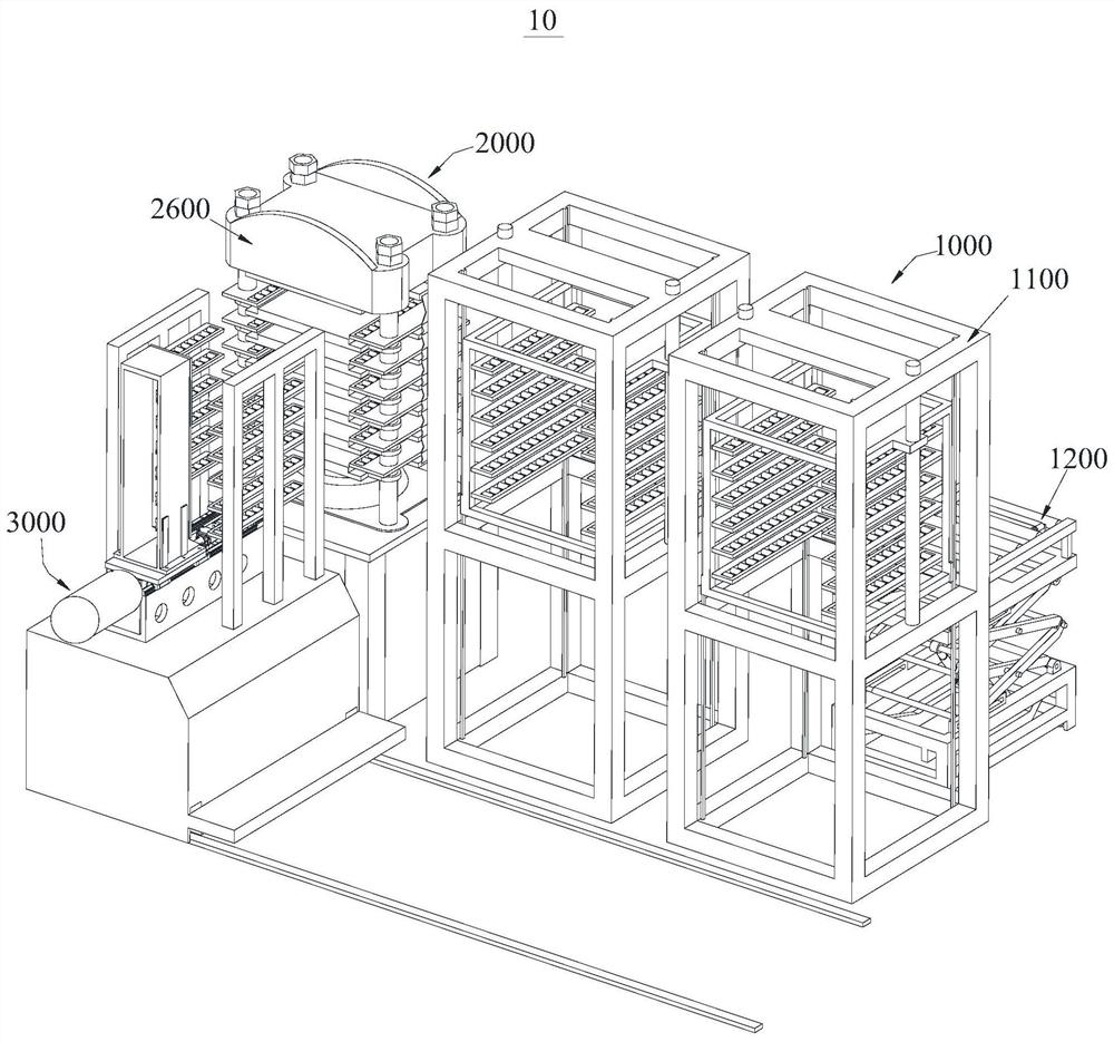
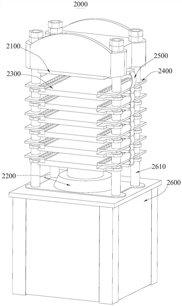
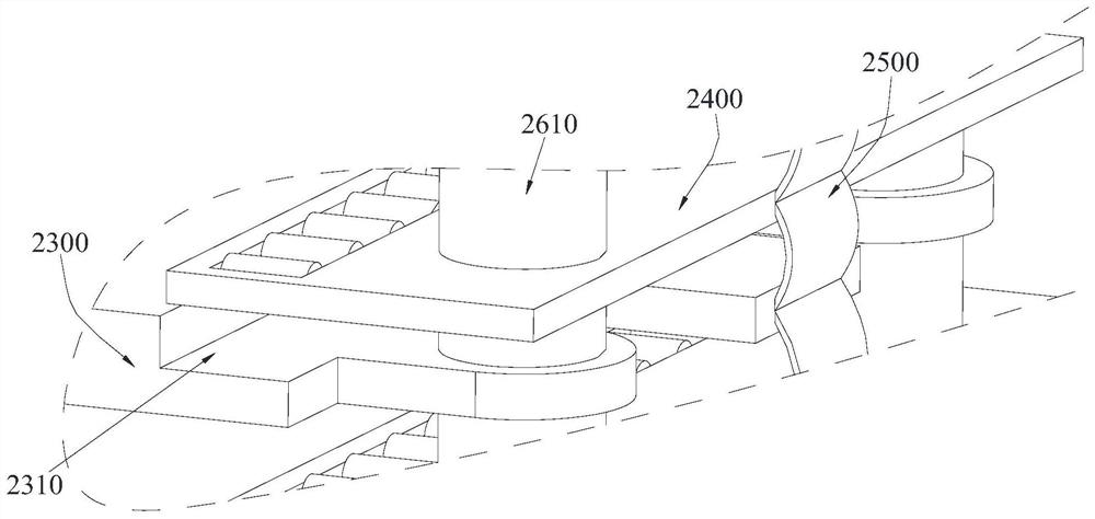
The invention provides multilayer circuit board laminating equipment, which comprises a transfer device, a laminating device and a transporting device, wherein the transfer device is used for bearinga multilayer board semi-finished product, the laminating device is used for carrying out laminating operation on the multilayer board semi-finished product, the transporting device is arranged betweenthe transfer device and the laminating device in a sliding mode, and is used for transporting the multilayer board semi-finished product to the laminating device from the transfer device, the laminating device comprises a top plate, a laminating driving piece, a laminated board, a sliding piece and a limiting belt, the limiting belt is sequentially connected with the top plate, the sliding pieceand the laminated board, and the laminating driving piece is connected with the laminated board and used for driving the laminated board to get close to the top plate, so that the sliding piece is accommodated in the laminated board. Through the arrangement of the sliding piece and the limiting belt, when the multilayer board semi-finished product is pushed in by the transporting device, abrasionbetween the multilayer board semi-finished product and the laminated board can be avoided, so that the laminating quality of the laminated board and the top board on the multilayer circuit board is effectively guaranteed.

Description

technical field [0001] The invention relates to the field of multilayer circuit board production, in particular to a multilayer circuit board pressing equipment. Background technique [0002] A circuit board usually refers to a printed circuit board. Specifically, a printed circuit board is formed by etching away unnecessary copper foil on the copper clad board, leaving only the required copper foil to form a circuit pattern. [0003] The circuit board can be divided into single-layer board, double-layer board and multi-layer board according to the structure. layer, while the multi-layer board is based on the double-layer board (at this time, the double-layer board is also called the core board), and the copper foil layer is sequentially added to the outside of the core board by using the prepreg, thereby making a multi-layer circuit board. . It should be noted that the prepreg and copper foil layers are applied sequentially on the core board, only the semi-finished multi-...

Claims


Application Information

Patent Timeline
Patent Type & Authority Applications(China)
IPC IPC(8): H05K3/46
CPCH05K3/4611H05K2203/068Y02P70/50
Inventor 张志刚陈文利
Owner HUIZHOU YUXINDA TECH CO LTD
Learn More