Fertilizer application device for agricultural farmland cultivation

A technology for farmland and chemical fertilizer, applied in the agricultural field, can solve the problems of inability to quantitatively fertilize and adjust the depth of ploughing

Active Publication Date: 2021-02-05
马亚军
View PDF9 Cites 2 Cited by
  • Summary
  • Abstract
  • Description
  • Claims
  • Application Information

AI Technical Summary

Problems solved by technology

[0005] In order to overcome the shortcomings that the existing fertilization device is not equipped with a chemical fertilizer burying device, cannot adjust the plow depth, and cannot apply fertilizer quantitatively, the technical problem of the present invention is: to provide a chemical fertilizer burying device, which can adjust the plow depth, and can also Applicable device for chemical fertilizers for agricultural farmland cultivation with quantitative fertilization

Method used


Image

  • Fertilizer application device for agricultural farmland cultivation
  • Fertilizer application device for agricultural farmland cultivation
  • Fertilizer application device for agricultural farmland cultivation

Examples


Embodiment 1

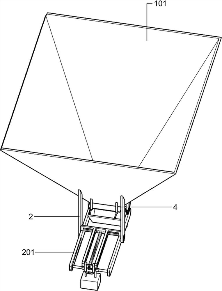
[0028] Applicable device for chemical fertilizers used in agricultural farmland cultivation, such as figure 1 As shown, it includes a vehicle frame 1, a hopper 101, a wheel 102, a control assembly, a trigger assembly and a dodge door assembly. Two groups of wheels 102 are arranged on the front and rear sides of the bottom of the vehicle frame 1, the hopper 101, the control assembly, the trigger assembly, There are three groups of dodge door assemblies and are arranged on the vehicle frame 1 at intervals. The hopper 101 is arranged in the middle part of the vehicle frame 1. A control assembly is arranged on the lower side of the hopper 101. The parts of the control assembly are fixedly connected on the hopper 101. The dodge door The assembly is arranged at the bottom of the hopper 101, the trigger assembly is fixedly connected to the control assembly, and the trigger assembly is in sliding contact with the movable door assembly.

[0029] Pour the chemical fertilizer into the ho...

Embodiment 2

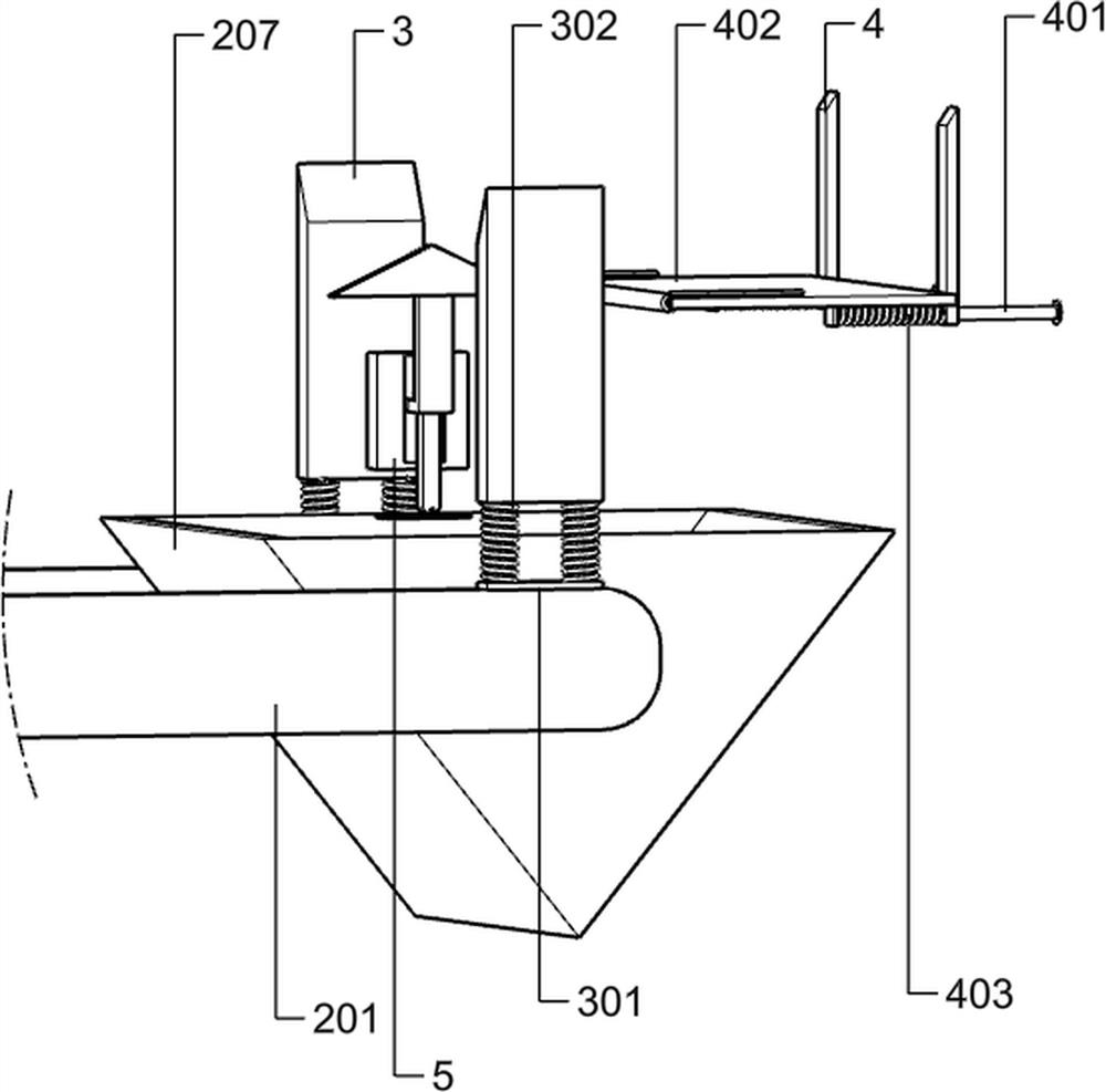
[0031] On the basis of Example 1, such as figure 2 As shown, the control assembly includes a vertical support plate 2, a horizontal support plate 201, a column 202, a counterweight 203, a connector 204, a T-shaped slider 205, an adjustment screw 206, a blanking funnel 207 and a buffer assembly. The upper end of the support plate 2 is fixedly connected to the outer wall of the hopper 101, the lower end of the vertical support plate 2 is rotatably connected with the horizontal support plate 201, the column 202 is slidingly connected in the groove on the horizontal support plate 201, and the counterweight 203 Rotationally connected to the middle of the cylinder 202, the T-shaped slider 205 is fixedly connected to the upper side of the horizontal support plate 201, the connector 204 is slidably connected to the groove of the T-shaped slider 205, and the left front end of the connector 204 is fixed with a counterweight Block 203, the adjusting screw rod 206 passes through the conn...

Embodiment 3

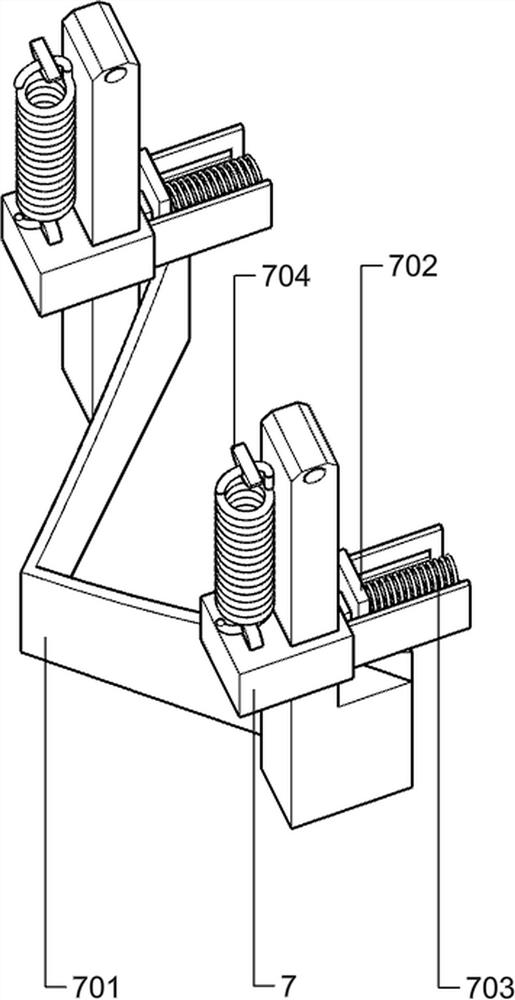
[0038] On the basis of Example 2, such as Figure 5 with image 3 As shown, the trigger assembly includes a square shell 5, a sliding column three 501, a push rod 502, a spring three 503, a roller 504 and a touch plate 505, the outer side of the square shell 5 is fixedly connected to the vertical support plate one 2, and the sliding column three 501 is fixedly connected to the inner bottom side of the square shell 5, the ejector rod 502 is slidably connected to the sliding column 3 501, the spring 3 503 is sleeved on the sliding column 3 501, and the lower end of the spring 3 503 is fixedly connected to the inner bottom side of the square shell 5, The upper end of the spring three 503 is in contact with the push rod 502, the lower end of the push rod 502 is rotatably connected with a roller 504, the outside of the touch plate is fixedly connected on the inner wall of the blanking funnel 207, and the touch plate 505 is in contact with the roller 504; the movable door assembly ...


PUM


Abstract

The invention relates to the field of agriculture, in particular to a fertilizer application device for agricultural farmland cultivation. The fertilizer application device for agricultural farmland cultivation is provided with a fertilizer burying device, the ploughing depth can be adjusted, and quantitative fertilization can be achieved. The fertilizer application device for agricultural farmland cultivation comprises a frame, wheels, hoppers,regulation and control assemblies and the like. Two groups of wheels are arranged at the bottom of the frame, the three groups of hoppers and the threegroups of regulation and control assemblies are arranged on the frame at intervals, the hoppers are arranged in the middle of the frame, and the regulation and control assemblies are arranged at onesides of the hoppers. The fertilization ratio of chemical fertilizer is regulated and controlled by adding the regulation and control assemblies, trigger assemblies and movable door assemblies, the regulation and control assemblies can regulate and control the fertilization ratio in advance, the trigger assemblies are matched with the movable door assemblies to achieve automatic fertilization, andquantitative and automatic fertilization of the device is achieved through the assemblies.

Description

technical field [0001] The invention relates to the field of agriculture, in particular to an application device for chemical fertilizers used in agricultural farmland cultivation. Background technique [0002] Granular fertilizer is an important agricultural resource, and solid granular fertilizer refers to compound fertilizer, potash fertilizer and other fertilizers. Fertilization refers to the agricultural technical measures that apply fertilizers to the soil or sprinkle them on plants to provide the nutrients needed by plants and maintain and improve soil fertility. Reasonable fertilization can increase crop yield, improve crop quality, fertilize soil and improve economic benefits. At present, the use of mechanical fertilization has become one of the main means to maintain the sustainable development of agriculture. [0003] After testing, as the patent publication number is CN111165141A patent, discloses a kind of solid granular fertilizer fertilization vehicle, compr...

Claims


Application Information

Patent Timeline
Patent Type & Authority Applications(China)
IPC IPC(8): A01C15/00A01C5/06
CPCA01C15/00A01C15/006A01C15/008A01C5/062A01C5/066
Inventor 张耘尧
Owner 马亚军
Why Eureka
Try Eureka