
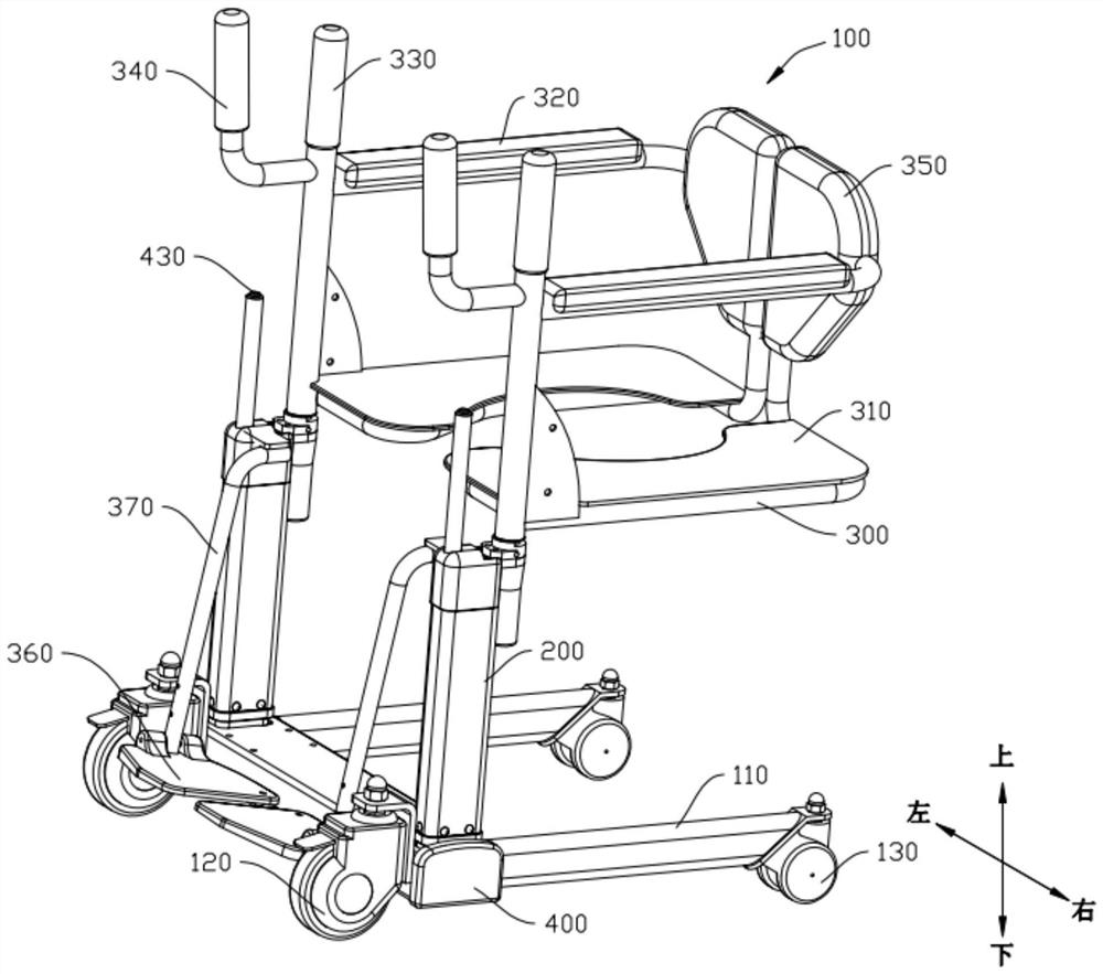
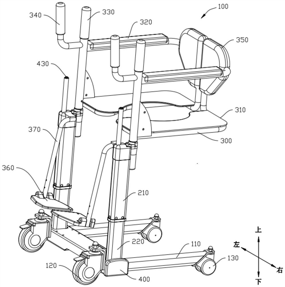
Liftable shifting machine

A technology of shifting machine and motor cover, which is applied in the field of medical equipment, which can solve the problems of insufficient bearing capacity of the lifting machine, easy damage to the lifting machine, and inconvenient use, so as to prevent the occurrence of startup failure, improve the bearing capacity, and facilitate operation Effect

Pending Publication Date: 2021-02-05
SILVERFOX CORP LTD
View PDF0 Cites 2 Cited by
  • Summary
  • Abstract
  • Description
  • Claims
  • Application Information

AI Technical Summary

Problems solved by technology

[0002] The lifting machine is used to help people with disabilities to move from wheelchairs to sofas, beds, toilets, seats, etc., and it adopts a plug-type lifting mechanism or a manual rocker-type lifting structure. In some cases, the lifting machine has insufficient bearing capacity, and it is easy to damage the lifting machine when adjusting the height, which is dangerous and inconvenient to use.

Method used


Image

  • Liftable shifting machine
  • Liftable shifting machine
  • Liftable shifting machine

Examples


Embodiment Construction

[0022] Embodiments of the present invention are described in detail below, examples of which are shown in the drawings, wherein the same or similar reference numerals designate the same or similar elements or elements having the same or similar functions throughout. The embodiments described below by referring to the figures are exemplary only for explaining the present invention and should not be construed as limiting the present invention.

[0023] In the description of the present invention, it should be understood that the orientation descriptions, such as up, down, front, back, left, right, etc. indicated orientations or positional relationships are based on the orientations or positional relationships shown in the drawings, and are only In order to facilitate the description of the present invention and simplify the description, it does not indicate or imply that the device or element referred to must have a specific orientation, be constructed and operated in a specific ...


PUM


Abstract

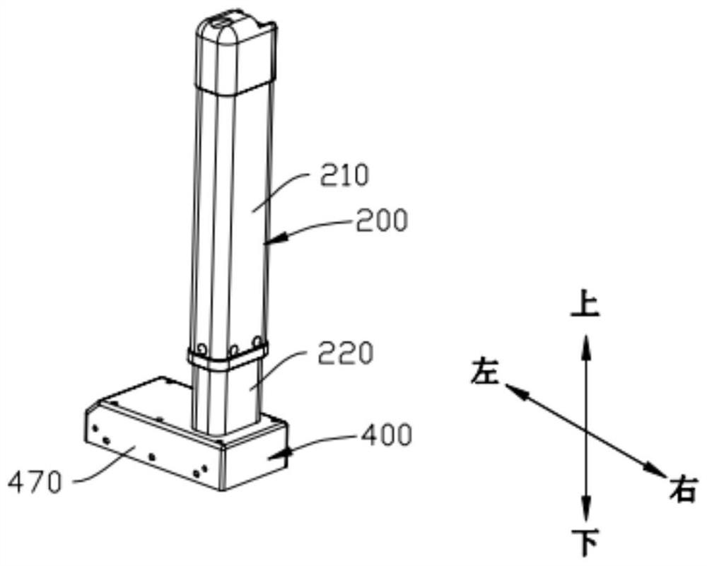
The invention discloses a liftable shifting machine. The machine comprises a controller, at least one supporting column and at least one motor assembly, wherein each supporting column comprises a first sleeve pipe and a second sleeve pipe; the first sleeve pipes are arranged on the second sleeve pipes in a sleeving mode; the motor assemblies are correspondingly connected with the supporting columns; each motor assembly comprises an independent motor and a supporting lifting rod which are connected with each other; the supporting lifting rods are connected with the first sleeve pipes; the supporting lifting rods are used for driving the second sleeve pipes to move along the first sleeve pipes under the driving of the independent motors so as to achieve lifting; and the controller is connected with the independent motors and used for controlling the independent motors to operate. The bearing capacity of the shifting machine can be improved by independent driving of the motors and sleeving cooperation of the supporting rods, the stability in a height adjusting process is improved, the situation that the shifting machine turns over or a user falls off from the shifting machine due to insufficient bearing capacity or stability of the shifting machine is prevented, and the safety of the shifting machine is improved.

Description

technical field [0001] The invention relates to the technical field of medical equipment, in particular to a liftable lifting machine. Background technique [0002] The lifting machine is used to help people with disabilities to move from wheelchairs to sofas, beds, toilets, seats, etc., and it adopts a plug-type lifting mechanism or a manual rocker-type lifting structure. In some cases, the lifting machine has insufficient bearing capacity, and it is easy to damage the lifting machine when adjusting the height, which is dangerous and inconvenient to use. Contents of the invention [0003] The present invention aims to solve at least one of the technical problems existing in the prior art. For this reason, the present invention proposes a liftable shifter, which improves the stability of the height adjustment process of the shifter, thereby improving the safety of the shifter. [0004] An embodiment of the present invention provides a lifting machine, including a control...

Claims


Application Information

Patent Timeline
Patent Type & Authority Applications(China)
IPC IPC(8): A61G7/10F16F15/04F16F15/08
CPCA61G7/1013A61G7/1073A61G7/1098A61G2203/72F16F15/04F16F15/08
Inventor 杨振宇谭剑锋袁健平
Owner SILVERFOX CORP LTD
Learn More