Withdrawal tool for friction stir welding stirring head

A technology of friction stir welding and stirring head, which is applied in welding equipment, manufacturing tools, non-electric welding equipment, etc. It can solve the problems of slow disassembly progress, unfavorable stirring head installation, and damage to the spindle hole of machine tools, and achieve the effect of avoiding damage

Inactive Publication Date: 2021-02-05
湖南坤鼎数控科技有限公司
View PDF5 Cites 0 Cited by
  • Summary
  • Abstract
  • Description
  • Claims
  • Application Information

AI Technical Summary

Problems solved by technology

[0004] The purpose of the present invention is to solve the problem that during the disassembly process, the disassembly process is slow with the help of auxiliary tools such as wooden hammers and pipe clamps, and the operation is easy to cause damage to the spindle hole of the machine tool, which is not conducive to the installation of a new stirring head. Stirring head unloading tool for friction stir welding

Method used


Image

  • Withdrawal tool for friction stir welding stirring head
  • Withdrawal tool for friction stir welding stirring head
  • Withdrawal tool for friction stir welding stirring head

Examples


Embodiment Construction

[0024] The following will clearly and completely describe the technical solutions in the embodiments of the present invention with reference to the accompanying drawings in the embodiments of the present invention. Obviously, the described embodiments are only some, not all, embodiments of the present invention. Based on the embodiments of the present invention, all other embodiments obtained by persons of ordinary skill in the art without making creative efforts belong to the protection scope of the present invention.

[0025] In the description of the present invention, it should be noted that the terms "center", "upper", "lower", "left", "right", "vertical", "horizontal", "inner", "outer" etc. The indicated orientation or positional relationship is based on the orientation or positional relationship shown in the drawings, and is only for the convenience of describing the present invention and simplifying the description, rather than indicating or implying that the referred d...


PUM


Abstract

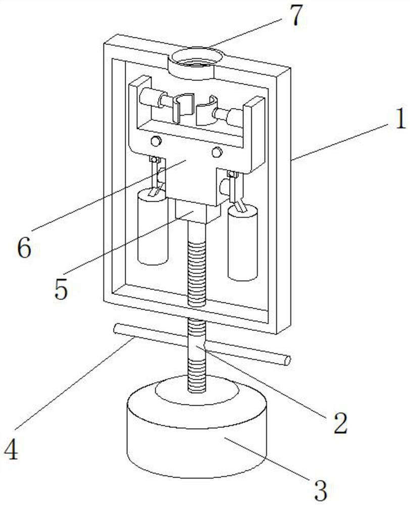
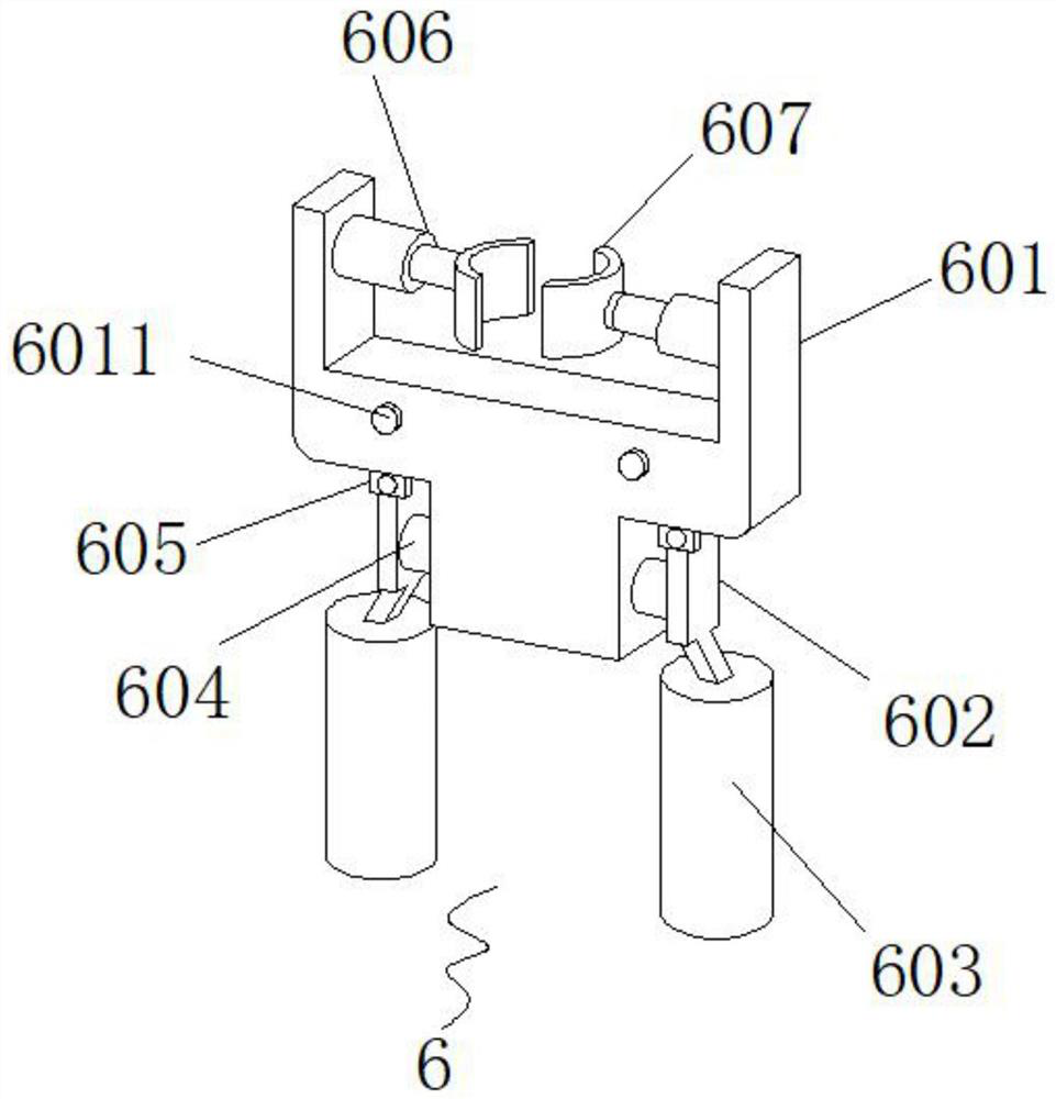
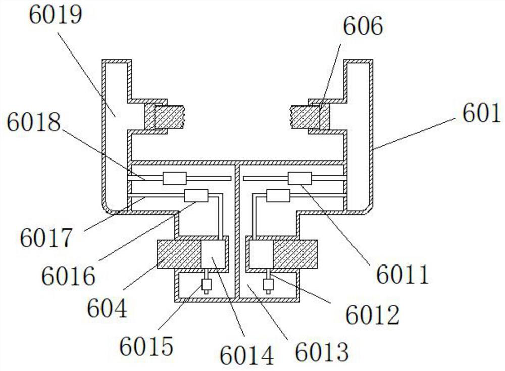
The invention relates to the field of friction stir welding, and discloses a withdrawal tool for a friction stir welding stirring head. The withdrawal tool comprises an outer frame, an annular block is arranged in the middle of the top end of the outer frame, a screw hole is formed in the middle of the bottom end of the outer frame, a T-shaped groove is formed in the upper surface of the annular block, and a screw is connected to the inner side of the screw hole in a penetrating mode. The upper end of the screw is connected with a fixing base, and rotating rods are connected to the positions,located between the outer frame and a base, of the two ends of the middle of the screw. The stirring head can be firmly clamped through a hydraulic clamping mechanism, then the slipping phenomenon cannot occur in the withdrawal process, the problem that the stirring head cannot be quickly withdrawn is solved, when a machine tool spindle descends to a certain position, the withdrawal tool can be buckled and fixed, then the screw is driven by the rotating rods to rotate, the screw drives the clamping mechanism to move downwards, and the stirring head is withdrawn from the machine tool spindle. Meanwhile, the problem that the machine tool spindle is damaged in the withdrawal process is also avoided.

Description

technical field [0001] The invention relates to the field of friction stir welding, in particular to a tool for removing and unloading a stirring head of friction stir welding. Background technique [0002] Friction welding is a method of using the heat generated by the mutual movement and friction of the workpiece ends to make the ends reach a thermoplastic state, and then quickly upset to complete the welding. The friction stir welding method is the same as the conventional friction welding. The friction stir welding also uses Friction heat and plastic deformation heat are used as welding heat sources. The difference is that the welding process of friction stir welding is that a cylinder or other shape (such as a threaded cylinder) of the stirring head is inserted into the joint of the workpiece, and the high-speed welding of the welding head Rotate to make it rub against the material of the welding workpiece, so that the temperature of the material at the joint will rise ...

Claims


Application Information

Patent Timeline
Patent Type & Authority Applications(China)
IPC IPC(8): B25B27/00B23K20/26B23K20/12
CPCB25B27/00B23K20/26B23K20/122
Inventor 吴靖凡雷勋发张新胜
Owner 湖南坤鼎数控科技有限公司
Why Eureka
Try Eureka