

Flow velocity detection device based on magnetic material
A magnetic material and detection device technology, applied in the field of flow velocity detection, can solve the problem of low detection accuracy and achieve the effect of high flow velocity detection accuracy
- Summary
- Abstract
- Description
- Claims
- Application Information
AI Technical Summary
Problems solved by technology
Method used
Image

Examples
Embodiment 1
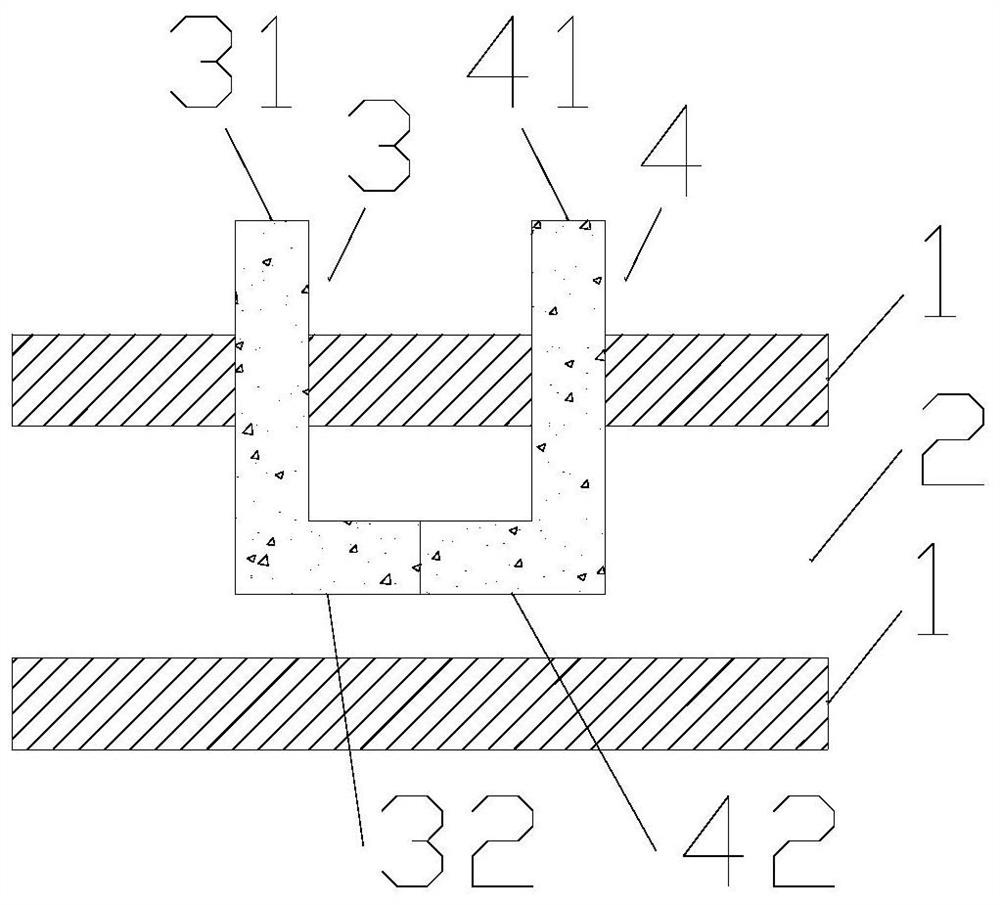
[0019] The invention provides a flow velocity detection device based on magnetic material. Such as figure 1 As shown, the magnetic material-based flow velocity detection device includes a cavity 1 , a first magnetic material part 3 , and a second magnetic material part 4 . The cavity 1 encloses a pipe 2, and the cross section of the pipe 2 can be square or circular, which is not limited here. A first through hole and a second through hole are provided on the cavity 1 along the direction of the pipeline 2 . That is to say, the first through hole and the second through hole are arranged along the flow square of the fluid. The distance between the first through hole and the second through hole is designed according to the specific flow rate, and is not specifically limited here. The shapes of the first through hole and the second through hole may be circular or square, which is not limited here. The first magnetic material part 3 and the second magnetic material part 4 pass t...
Embodiment 2
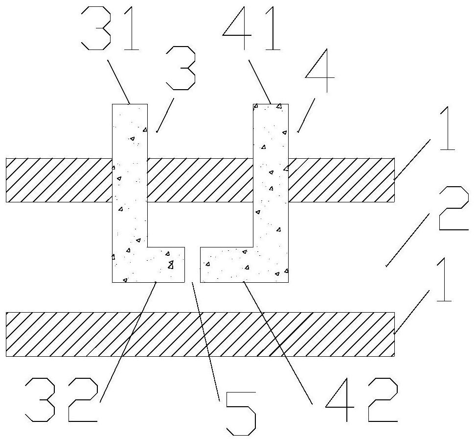
[0022] On the basis of Example 1, such as figure 2 As shown, there is a gap 5 between the other end of the first horizontal portion 32 and the other end of the second horizontal portion 42 . In this way, under the action of the fluid, the width of the gap 5 changes, thereby changing the reluctance of the section of the magnetic circuit formed by the first magnetic material part 3 and the second magnetic material part 4 . Because the magnetic resistance of the gap 5 is very sensitive to the width of the gap 5 , this embodiment can further improve the accuracy of flow velocity detection.
[0023] Furthermore, the diameter of the first vertical portion 31 is different from that of the second vertical portion 41 . In this way, under the action of the fluid, the deflection conditions of the first vertical portion 31 and the second vertical portion 41 are different, so as to change the width of the gap 5 more, thereby achieving higher precision flow velocity detection.
Embodiment 3
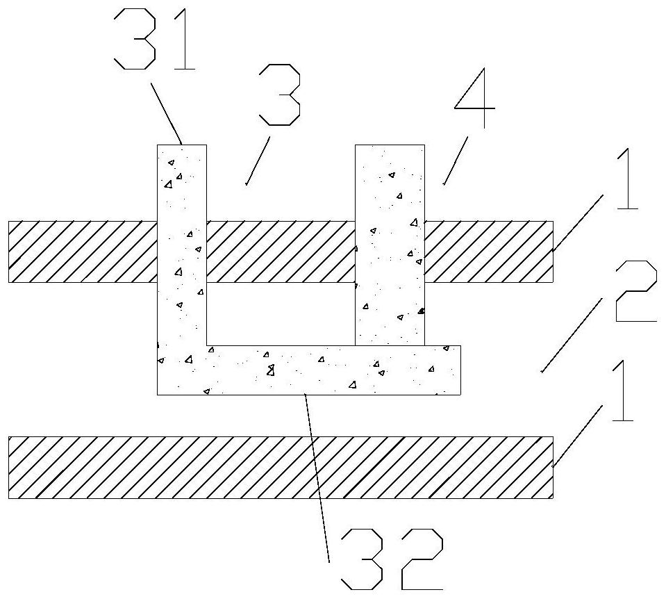
[0025] On the basis of Example 1, such as image 3 As shown, the first magnetic material part 3 includes a first vertical part 31 and a first horizontal part 32, the first vertical part 31 passes through the first through hole, and in the pipeline 2, one end of the first vertical part 31 is connected to the first One end of a horizontal portion 32 is fixedly connected. The second magnetic material portion 4 is strip-shaped, that is to say the second magnetic material portion 4 is only image 3 middle vertical part. The second magnetic material part 4 vertically passes through the second through hole. In the pipe 2 , one end of the second magnetic material part 4 is in contact with the side of the first horizontal part 32 , but is not fixedly connected. Under the action of the fluid, the second magnetic material part 4 changes its position relative to the side of the first horizontal part 32 . In this way, the length of the first horizontal portion 32 involved in the magneti...
PUM
 Abstract
Description
Claims
Application Information