Rotary electric machine stator and rotary electric machine provided with same

A technology for rotating electrical machines and stators, which is used in the manufacture of motor generators, electromechanical devices, electrical components, etc., can solve the problems of thermal damage to insulating films, easy reduction of stator coil manufacturing yields, and reduced electrical insulation, and achieves low cost. Effect

Pending Publication Date: 2021-02-05
HITACHI ASTEMO LTD
View PDF7 Cites 0 Cited by
  • Summary
  • Abstract
  • Description
  • Claims
  • Application Information

AI Technical Summary

Problems solved by technology

[0003] In recent years, the miniaturization of rotating electric machines (especially the shortening of the length in the direction of the rotating shaft) has been urgently required, and the winding method of the stator coil has become complicated in order to meet this demand.
In addition, in rotating electrical machines, there is a strong demand for cost reduction, but the manufacturing yield tends to decrease due to the complexity of the winding method of the stator coil, and the improvement of the manufacturability of the stator is a problem.
For example, in the process of welding the segment conductors at the end of the stator coil, the insulating film of the segment conductors may be thermally damaged. As a result, there is a problem that the electrical insulation between the segment conductors that should be electrically insulated decreases.

Method used


Image

  • Rotary electric machine stator and rotary electric machine provided with same
  • Rotary electric machine stator and rotary electric machine provided with same
  • Rotary electric machine stator and rotary electric machine provided with same

Examples


no. 1 Embodiment approach

[0057] (rotating motor)

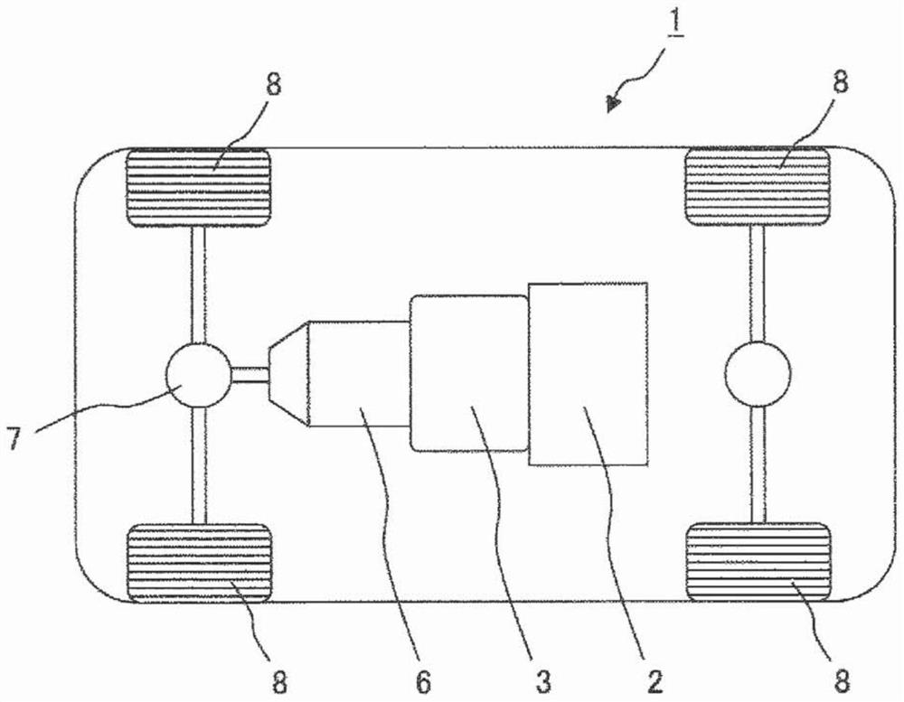
[0058] figure 1 It is an example of a block diagram of a hybrid electric vehicle equipped with a rotary electric machine according to the present invention. like figure 1 As shown, a vehicle 1 of a hybrid electric vehicle is equipped with an engine 2 and a rotating electric machine 3 as power sources of a vehicle drive system. The rotational torque generated by the engine 2 and the rotary electric machine 3 is transmitted to wheels (drive wheels 8 ) via a transmission 6 (for example, a continuously variable transmission, a stepped transmission) and a differential gear 7 . The rotary electric machine 3 is usually installed between the engine 2 and the transmission 6 or mounted on the transmission 6 . Therefore, the rotary electric machine 3 is required to be smaller and higher in output in order to minimize the space occupied in the vehicle 1 and to increase the driving force.

[0059] In addition, although figure 1 Not shown in , but it is also p...

no. 2 Embodiment approach

[0104] Compared with 1st Embodiment, 2nd Embodiment differs only in the form of the exposed part of the conductor wire which forms the welding part of a stator coil, and is the same in all other things. Therefore, only the form of the welded portion and the exposed portion of the conductor wire will be described.

[0105] Figure 9 It is an enlarged schematic side view showing an example of a welded portion of a stator coil in the second embodiment. like Figure 9 As shown, the welding part 334' of the stator coil 331' according to the second embodiment is characterized in that only one conductor wire exposed part 343' of the paired segment conductors 333' constituting the welding part 334' has a root 343b , the transfer portion 343t and the junction portion 343j , the junction portion 343j is offset by a displacement x of “2±0.4 times” the thickness of the insulating film 342 in the radial direction relative to the root portion 343b . The shift amount x is more preferably ...


PUM


Abstract

The present invention addresses the problem of providing a rotary electric machine stator and a rotary electric machine provided with the stator in which downsizing, a high output, and cost reductioncan be achieved with good balance at a high level, compared to the conventional technology. The rotary electric machine stator according to the present invention is formed by winding a stator coil around a stator core, and is characterized in that: in the stator coil, welded portions between segment conductors are each formed in the region of an end portion of the stator coil; the segment conductors each have, at a portion near the corresponding welded portion, a conductor wire exposed portion where an insulating coating provided on the outer circumference of the conductor wire has been removed; in each of the welded portions, the conductor wire exposed portion of at least one of paired segment conductors constituting the welded portion, includes a root section that is adjacent to the insulating coating along the longitudinal direction of the conductor wire, a transition section for radially offsetting the center axis of the conductor wire by a prescribed displacement amount, and a joined section that is radially offset from the root section by the prescribed displacement amount; press marks exist at the boundary between the root section and the transition section and at the boundary between the transition section and the joined section; and the prescribed displacement amount is 1+-0.4 times or 2+-0.4 times of the thickness of the insulating coating.

Description

technical field [0001] The present invention relates to technologies related to rotating electric machines, and in particular, to a stator that contributes to downsizing and higher output of a rotating electric machine, and a rotating electric machine including the same. Background technique [0002] As a type of rotating electric machine (for example, electric motor), there is a winding field type rotating electric machine. A wound field type rotating electrical machine is a mechanism in which stator coils are arranged in a plurality of stator slots formed in a stator core, and when a voltage is applied to the stator coils, a rotating magnetic field is generated, and the rotor rotates by the rotating magnetic field. [0003] In recent years, there has been a strong demand for downsizing (in particular, shortening of the length in the direction of the rotating shaft) of rotating electric machines, and the winding method of the stator coil has become complicated in order to m...

Claims


Application Information

Patent Timeline
Patent Type & Authority Applications(China)
IPC IPC(8): H02K3/04H02K15/04H02K15/085
CPCH02K15/0081H02K2213/03H02K1/16H02K3/02H02K3/12H02K3/28H02K3/38H02K3/48H02K3/50H02K15/024H02K15/105
Inventor 福田知纮小野濑伸金野雄志岛田康弘中山健一清水尚也桥本光惠
Owner HITACHI ASTEMO LTD
Why Eureka
Try Eureka