Rotating bias drive mechanism

A driving mechanism and offset technology, which is applied in the fields of transmission, mechanical equipment, medical science, etc., can solve the problems that the rotating shaft is easily affected by eccentric force and the demand for installation space is large, so as to reduce the cost and the demand for installation space, and improve Stability and service life, the effect of ensuring stability

Pending Publication Date: 2021-02-09
合肥哈工慈健智能科技有限公司
View PDF1 Cites 2 Cited by
  • Summary
  • Abstract
  • Description
  • Claims
  • Application Information

AI Technical Summary

Problems solved by technology

[0004] The technical problem to be solved by the present invention is to provide a rotary offset driving mechanism that uses an offset structure to drive the bed board to move and can be locked during rotation in view of the problems of the prior art that the installation space is large and the rotating shaft is easily affected by eccentric force

Method used


Image

  • Rotating bias drive mechanism
  • Rotating bias drive mechanism
  • Rotating bias drive mechanism

Examples


Embodiment Construction

[0022] In order to make the purpose, technical solutions and advantages of the present invention clearer, the technical solutions of the present invention are clearly and completely described below in conjunction with specific embodiments and with reference to the accompanying drawings. Obviously, the described embodiments are part of the implementation of the present invention. example, not all examples. Based on the embodiments of the present invention, all other embodiments obtained by persons of ordinary skill in the art without creative efforts fall within the protection scope of the present invention.

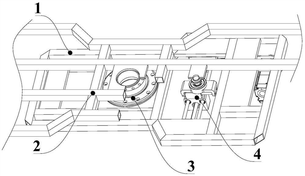
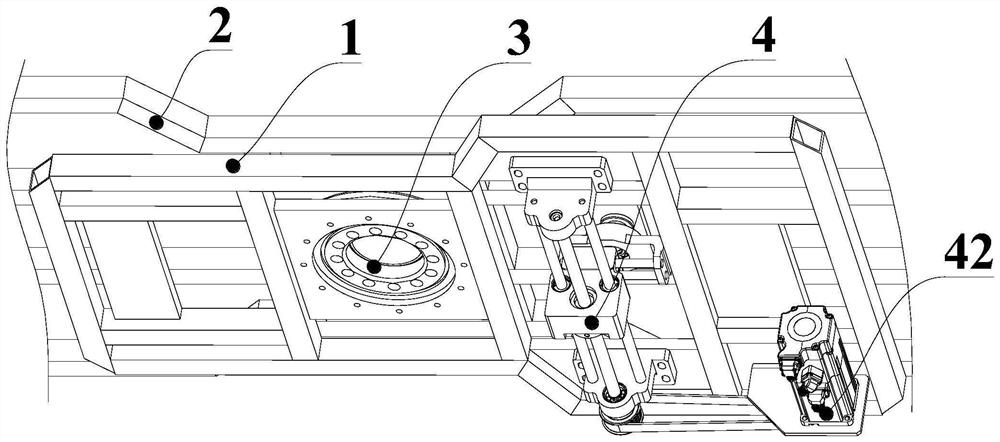
[0023] Such as figure 1 As shown, the present embodiment provides a rotational bias driving mechanism, which includes a fixed frame 1 and a rotating frame 2 whose surfaces are parallel to each other, and the fixed frame 1 is fixedly provided with a support member 3 and a driving frame connected to the rotating frame 2 respectively. Part 4, the rotating frame 2 can freely...


PUM


Abstract

The invention provides a rotating bias drive mechanism. The mechanism comprises a fixed frame and a rotating frame, the surfaces of the fixed frame and the rotating frame are parallel to each other, asupporting component and a driving component which are connected with the rotating frame are fixedly arranged on the fixed frame, and the rotating frame can freely rotate in a plane relative to the supporting component and the driving component. The driving component comprises driving shafts matched with the rotating frame, the positions of the driving shafts can be changed in the rotating planeof the rotating frame under the action of the driving component, and the driving component can lock the positions of the driving shafts. The mechanism has the advantages that two rotating centers areprovided for the rotating frame, and the position of one driving shaft is changed by the driving component, so that the rotating frame rotates relative to the supporting component in the plane, the influence of eccentric force on the service life of the rotating shaft under the condition of a single rotating shaft is overcome, the stability is improved, and the service life is prolonged; and the driving shafts can be fixed at any position within the moving range, so that the rotating frame cannot shake in the using process, and safety is improved.

Description

technical field [0001] The invention relates to the technical field of rotary drive mechanisms, in particular to a rotary bias drive mechanism. Background technique [0002] With the increase of the aging population, there are more and more people with limited mobility. Many patients can only stay in bed for a long time. Nursing and other work; the existing equipment mostly adopts the structure of motor direct drive, or the motor, reducer and rotating shaft adopt a series structure, which occupies a large space in the axial direction and requires a large installation space. Some equipment uses a rotating shaft and a reducer in series. The input shaft of the reducer and the motor are driven by a synchronous belt drive, and the central axis of the rotating shaft is the input point of the maximum torque position. To meet the torque demand, a larger reducer is required. There is no doubt that the cost will increase, and the large torque reducer also needs to occupy a large inst...

Claims


Application Information

Patent Timeline
Patent Type & Authority Applications(China)
IPC IPC(8): A61G7/05A61G7/015F16H37/12
CPCA61G7/015A61G7/05F16H37/124
Inventor 张岩岭姜祖辉于振中李文兴
Owner 合肥哈工慈健智能科技有限公司
Why Eureka
Try Eureka