Feeding and discharging device for 3C electronic product production

A technology for electronic products and horizontal plates, which is applied in the field of loading and unloading devices for 3C electronic product production, which can solve the problems of high fixture manufacturing and maintenance costs, increased fixture failure rate, and low automation, and achieves simple structure and reduced use and maintenance costs. , the effect of improving efficiency

Pending Publication Date: 2021-02-09
程俊为
View PDF7 Cites 2 Cited by
  • Summary
  • Abstract
  • Description
  • Claims
  • Application Information

AI Technical Summary

Problems solved by technology

The 3C electronic product industry is characterized by a high degree of automation. A large number of automated production equipment are used in the production process of such products. 3C electronic products are also characterized by small size and large quantity. This requires zero The manufacturing, transportation and even assembly of components must have high efficiency. At present, when loading and unloading materials during the assembly process of 3C electronic product parts, the existing technical equipment has a low degree of automation, and it is impossible to achieve simultaneous loading and unloading during the loading and unloading process. Multiple accessories located on a straight line are transferred, and in the existing clamping equipment, pressure sensors are generally used to control the clamping force of the jaws, but in actual use, pressure sensors are installed on multiple jaws, resulting in clamping The manufacturing and maintenance costs are high, and the failure rate of the fixture is also increased

Method used


Image

  • Feeding and discharging device for 3C electronic product production
  • Feeding and discharging device for 3C electronic product production
  • Feeding and discharging device for 3C electronic product production

Examples


Embodiment 1

[0025] Such as figure 1 shown;

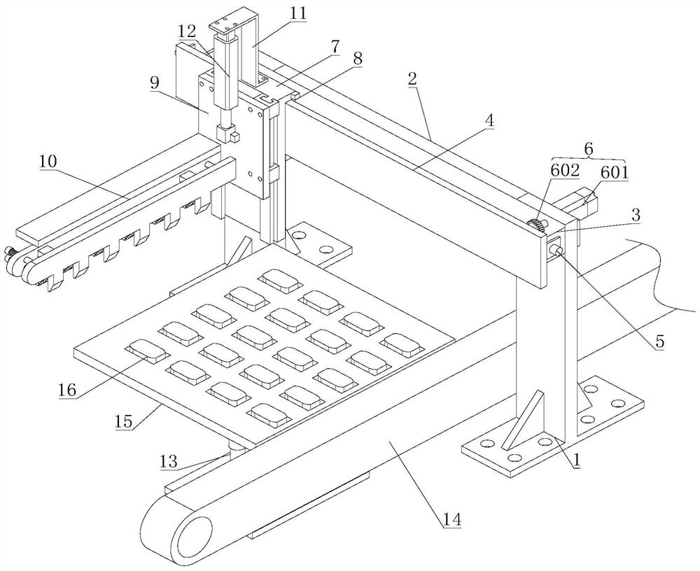
[0026] figure 1 It is a structural schematic diagram of the present invention.

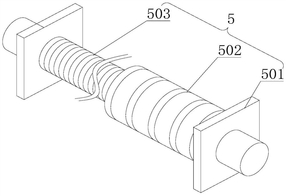
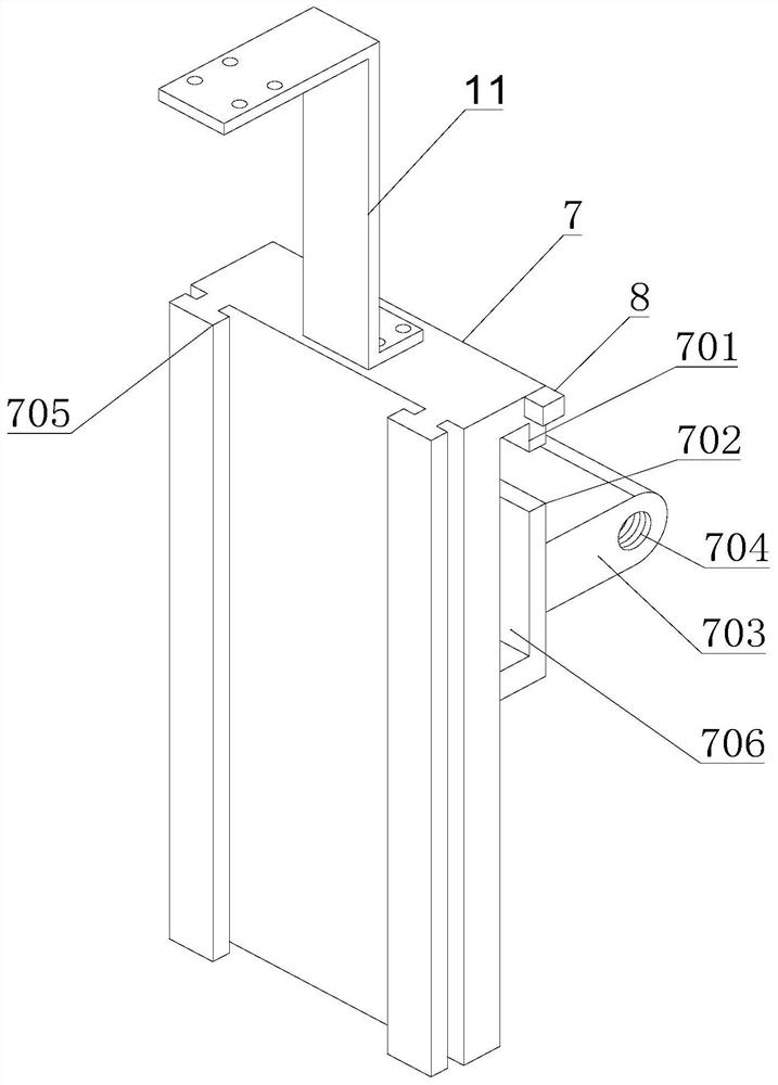
[0027] A loading and unloading device for 3C electronic product production, comprising two symmetrical fixed seats 1, characterized in that: the top ends of the two fixed seats 1 are fixedly connected by a horizontal plate 2, and one side of the horizontal plate 2 is symmetrically provided with End plate 3, the end of the end plate 3 away from the horizontal plate 2 is provided with a support plate 4, a worm assembly 5 is arranged between the two end plates 3, one side of the horizontal plate 2 is located on the fixed The top of the seat 1 is provided with a servo drive mechanism 6, and the servo drive mechanism 6 is matched with the worm assembly 5, and the side of the support plate 4 away from the horizontal plate 2 is provided with a clamping plate 7, the clamping plate One side of 7 is provided with a displacement sensor 8, and the clamping plate 7 and the s...


PUM


Abstract

The invention belongs to the technical field of electronic product production equipment, and particularly relates to a feeding and discharging device for 3C electronic product production. The feedingand discharging device comprises two symmetrically-arranged fixing seats, the top ends of the two fixing seats are fixedly connected through a transverse plate, end plates are symmetrically arranged on one side of the transverse plate, supporting plates are arranged at the ends, away from the transverse plate, of the end plates, and a worm assembly is arranged between the two end plates. A servo driving mechanism is arranged in the position, located at the tops of the fixing seats, of one side of the transverse plate, the servo driving mechanism is matched with the worm assembly, clamping plates are arranged on the sides, deviating from the transverse plate, of the supporting plates, first displacement sensors are arranged on one sides of the clamping plates, the clamping plates are slidably connected with the supporting plates, and the clamping plates are in threaded connection with the worm assembly. Sliding table mechanisms are symmetrically arranged on the side faces of the sides,away from the supporting plates, of the clamping plates. The feeding and discharging device is simple in structure and reasonable in design, the use and maintenance cost of equipment is reduced, the efficiency of feeding and discharging materials in the production process of 3C electronic products is improved, and the positioning precision of the feeding and discharging device is improved.

Description

technical field [0001] The invention belongs to the technical field of electronic product production equipment, and in particular relates to a loading and unloading device for 3C electronic product production. Background technique [0002] 3C electronic products are the abbreviations of three types of electronic products: Computer, Communication and Consumer Electronics. Now many IT industries are marching into the field of digital 3C one after another, taking digital 3C fusion technology products as the breakthrough point of development and becoming a new bright spot in the IT industry. The 3C electronic product industry is characterized by a high degree of automation. A large number of automated production equipment are used in the production process of such products. 3C electronic products are also characterized by small size and large quantity. This requires zero The manufacturing, transportation and even assembly of components must have high efficiency. At present, whe...

Claims


Application Information

Patent Timeline
Patent Type & Authority Applications(China)
IPC IPC(8): B65G47/90
CPCB65G47/901B65G47/907
Inventor 程俊为
Owner 程俊为
Why Eureka
Try Eureka