
Turnover device for precision shaft production

A precision shaft and turnover box technology, applied in the direction of conveyor control devices, transportation and packaging, conveyor objects, etc., can solve problems that affect corporate image, missed inspections, and unqualified products leave the factory, and achieve the effect of convenient turnover transportation

Active Publication Date: 2021-02-09
SHANDONG TRANSPORT VOCATIONAL COLLEGE
View PDF10 Cites 0 Cited by
  • Summary
  • Abstract
  • Description
  • Claims
  • Application Information

AI Technical Summary

Problems solved by technology

[0004] However, the above-mentioned existing technology has the following disadvantages: When the operator performs quality inspection on the precision shaft, he often only detects items such as roundness runout and surface roughness of the precision shaft, and often ignores the length with relatively low accuracy requirements, resulting in missed inspections , so that unqualified products leave the factory, causing economic losses and affecting the corporate image

Method used


Image

  • Turnover device for precision shaft production
  • Turnover device for precision shaft production
  • Turnover device for precision shaft production

Examples


Embodiment

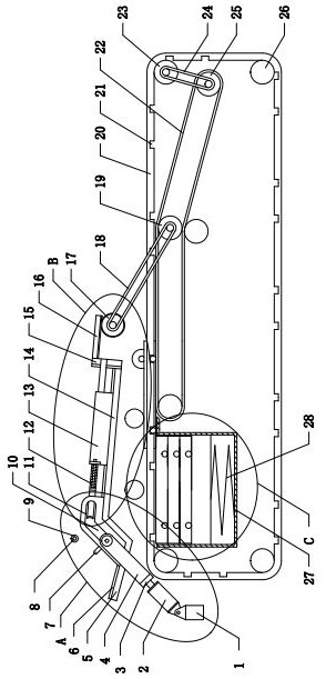
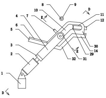
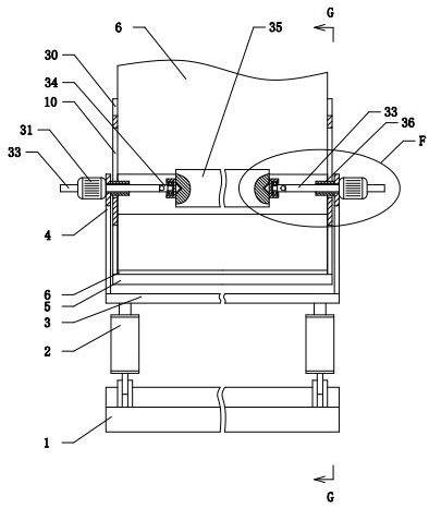
[0033] Example: as attached Figures 1 to 7 As shown, a turnover device for precision shaft production includes a frame, and the frame is provided with a first pallet 5 and a second pallet 32 ​​arranged obliquely. The lower end of the first pallet 5 is connected to the second pallet 32. The lower ends of the supporting plates 32 are connected, and the first supporting plate 5 and the second supporting plate 32 form a V-shaped structure for placing the precision shaft 35 . The upper end of the second supporting plate 32 is provided with a sloping plate 14, and the first supporting plate 5, the second supporting plate 32 and the sloping plate 14 are all provided with a sponge pad 6 to prevent the precision shaft 35 from contacting the first supporting plate. Plate 5, second supporting plate 32 or slope plate 14 collide, causing precision shaft 35 to be damaged. Below the lower end of the ramp 14 is provided a turnover box 51 capable of holding the precision shaft 35. When the p...


PUM


Abstract

The invention provides a turnover device for precision shaft production. The turnover device comprises a rack, wherein a first supporting plate and a second supporting plate which are obliquely arranged are arranged on the rack; a slope plate which is obliquely arranged is arranged at the upper end of the second supporting plate; a turnover box is arranged below the slope plate; a guide plate is arranged on the edge of the second supporting plate; a first guide groove and a second guide groove are formed in the guide plate; an oil cylinder is hinged to the rack; two motor brackets are arrangedon an ejector rod of the oil cylinder; sliding cylinders capable of moving along the first guide groove and the second guide groove are arranged on the motor brackets; linear motors are arranged on the outer sides of the motor brackets; a conductive part is arranged at one end, penetrating through the corresponding sliding cylinder, of a motor push rod; an electric brush is arranged on the side part of each conductive part; two conductive shafts are arranged above the second supporting plate; an insulating interval is formed between the two conductive shafts; an insulating part is arranged oneach conductive shaft; and a power supply and an alarm lamp are connected between the two conductive shafts through wires. When the length of a precision shaft does not meet the standard, the alarm lamp works to remind an operator to pay attention; meanwhile, the precision shaft falls into the turnover box, so that turnover transportation is facilitated.

Description

technical field [0001] The invention relates to the technical field of precision shaft production equipment. [0002] Specifically, it relates to a rotary device for precision shaft production. Background technique [0003] The precision shaft is a shaft with high precision requirements such as roundness and runout, and has a wide range of applications in the machinery industry. In the existing technology, when the precision shaft is processed, every time a process is completed, the operator needs to put the precision shaft into the turnover box, and then transport it to the station of the next process. Finally, the operator needs to perform quality inspection on the precision shaft. To test whether the precision shaft is qualified. [0004] However, the above-mentioned existing technology has the following disadvantages: When the operator performs quality inspection on the precision shaft, he often only detects items such as roundness runout and surface roughness of the p...

Claims


Application Information

Patent Timeline
Patent Type & Authority Applications(China)
IPC IPC(8): B65G47/90B65G43/08B07C5/34B07C5/38
CPCB07C5/34B07C5/38B65G43/08B65G47/90
Inventor 赵益涛李付君孙亚楠
Owner SHANDONG TRANSPORT VOCATIONAL COLLEGE
Learn More