Beater for papermaking

A technology of beater and box, which is applied in the field of beater for papermaking, and can solve the problems of not being able to improve the uniformity of mixing and unfavorable working efficiency of the beater

Inactive Publication Date: 2021-02-09
文芬芳
View PDF0 Cites 0 Cited by
  • Summary
  • Abstract
  • Description
  • Claims
  • Application Information

AI Technical Summary

Problems solved by technology

When the existing beater is beating, the stirring rod can only rotate fixedly, which cannot improve the uniformity of stirring, and is not conducive to improving the working efficiency of the beater

Method used


Image

  • Beater for papermaking
  • Beater for papermaking

Examples


Embodiment Construction

[0015] The following will clearly and completely describe the technical solutions in the embodiments of the present invention with reference to the accompanying drawings in the embodiments of the present invention. Obviously, the described embodiments are only some, not all, embodiments of the present invention. Based on the embodiments of the present invention, all other embodiments obtained by persons of ordinary skill in the art without making creative efforts belong to the protection scope of the present invention.

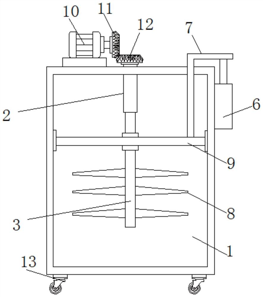
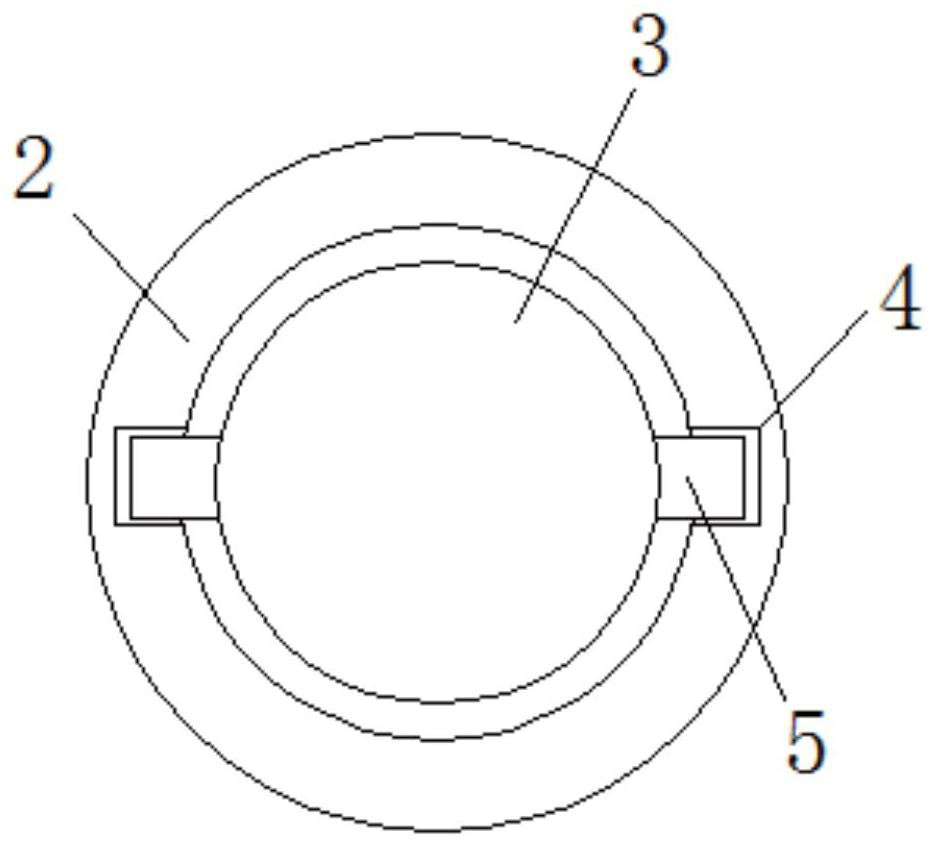
[0016] see Figure 1-2 , the present invention provides a technical solution: a pulper for papermaking, including a box body 1: a cylinder 2 runs through the top of the inner cavity of the box body 1, a cylinder 3 is arranged inside the cylinder 2, and the bottom end of the cylinder 3 Located inside the box 1, a chute 4 is vertically opened inside the cylinder 2, a slider 5 is fixedly installed on the peripheral side of the cylinder 3, and the slider 5 is inse...


PUM


Abstract

The invention discloses abeaterfor papermaking. The beater comprises a box body, wherein a barrel penetrates through the top of an inner cavity of the box body; a cylinder is arranged in the barrel; the bottom end of the cylinder is located in the box body; a sliding groove is vertically formed in the barrel; a sliding block is fixedly installed on the peripheral side of the cylinder and is inserted into the sliding groove; a telescopic air cylinder is fixedly installed on the right side of the box body; an L-shaped rod is fixedly mounted at the top of the telescopic air cylinder; the bottom end of a vertical rod of the L-shaped rod penetrates through the top plate of the box body and extends into the box body; a lifting rod sleeves the periphery of the cylinder; two ends of the lifting rod are slidably connected with the inner wall of the box; the lifting rod is rotatably connected with the L-shaped rod through a bearing; and the bottom end of the vertical rod of the L-shaped rod is fixedly connected with the lifting rod. By arranging a hydraulic air cylinder, the hydraulic air cylinder drives the cylinder and beating rods to move up and down through the L-shaped rod and the lifting rod, so the beating rods can move up and down while rotating, beating efficiency is improved, and benefits are improved.

Description

technical field [0001] The invention relates to the technical field of beating machines, in particular to a beating machine for papermaking. Background technique [0002] After the material enters the screen cylinder, due to the rotation of the stick and the existence of the lead angle, the material moves along the cylinder to the outlet end. The trajectory is a helical line. The material is subjected to centrifugal force during the movement between the scraper and the screen cylinder. The paper pulp circulates in the groove, and through the action between the flying knife and the bottom knife, it produces transverse cutting, longitudinal splitting, crushing, swelling (swelling), etc., so as to make paper that meets the requirements of papermaking. slurry. When the existing beater is beating, the stirring rod can only rotate fixedly, which cannot improve the uniformity of stirring, and is not conducive to improving the working efficiency of the beater. Contents of the inv...

Claims


Application Information

Patent Timeline
IPC IPC(8): D21D1/02
CPCD21D1/02
Inventor 文芬芳
Owner 文芬芳
Why Eureka
Try Eureka