Pulping device for papermaking

The technology of a stirring device and a power device is applied in the field of beating devices for papermaking, which can solve the problems of complex structure, crushing dead ends, single beating blades, etc., and achieve the effects of good beating effect, large impact force and improving beating efficiency.

Inactive Publication Date: 2021-02-12
程新钟
View PDF9 Cites 2 Cited by
  • Summary
  • Abstract
  • Description
  • Claims
  • Application Information

AI Technical Summary

Problems solved by technology

[0003] At present, the commonly used beater has complex structure and low work efficiency. By prolonging the working time to meet the beating requirements, a lot of time is wasted. In addition, the existing beater only works through a single work of the beating blade, and it is easy to form a crushing dead angle inside, resulting in beating There are still a lot of raw materials in the end, which is due to incomplete processing, resulting in waste of resources

Method used


Image

  • Pulping device for papermaking
  • Pulping device for papermaking
  • Pulping device for papermaking

Examples


Embodiment 1

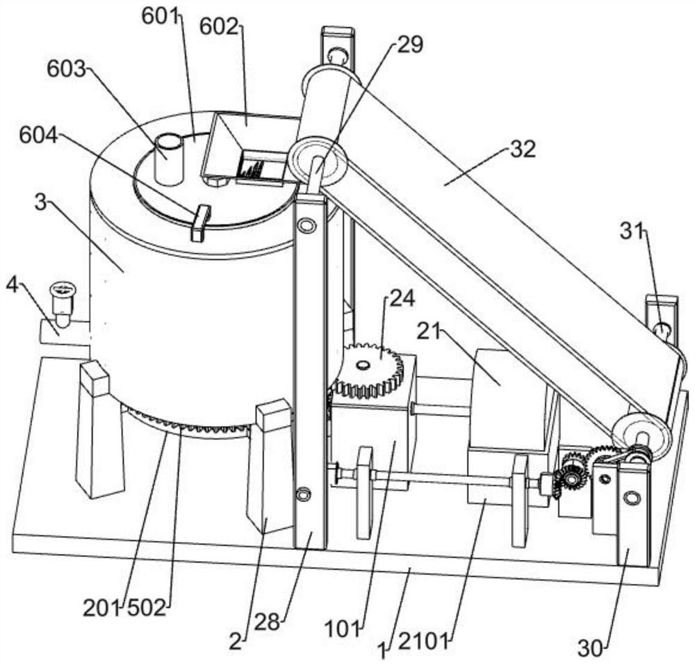
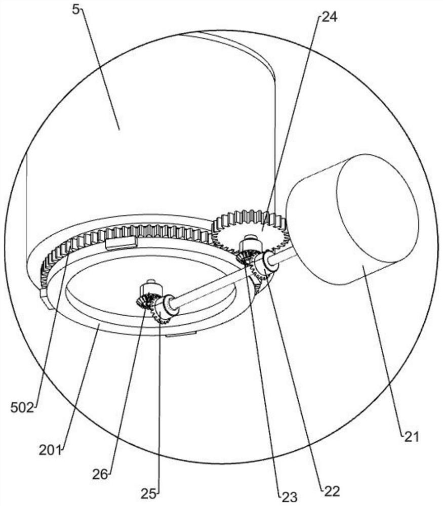
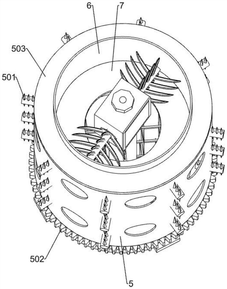
[0028] A pulping device for papermaking, such as Figure 1-7 As shown, it includes a bottom plate 1, a support block 2, a base 201, an outer box 3, a discharge port 4, an upper cover plate 601, a feed port 602, a water injection port 603, a handle 604, a power device, a stirring device and a chopper The device, four support blocks 2 are fixedly installed on the bottom plate 1, a base 201 is fixedly installed on the inner side wall of the four support blocks 2, an outer box 3 is fixedly installed above the base 201, and the left side wall of the outer box 3 is fixedly installed There is a discharge port 4, a handle 604 is symmetrically installed above the upper cover 601, the rear end of the handle 604 is fixedly connected with the upper cover 601, the front end of the handle 604 is in contact with the top of the outer box 3, and a note is installed on the upper left of the upper cover 601. The water port 603 and the feed port 602, the power device is installed on the upper rig...

Embodiment 2

[0039] On the basis of Example 1, as Figure 8-9 Shown, also include 28-large straight column 28,29-the first connecting shaft 29,30-small straight column 30,31-second connecting shaft 31 and 32-conveyor belt 32, two big straight columns 28 are fixedly installed on Above the middle part of the bottom plate 1, a first connecting shaft 29 is installed between the two large straight columns 28, the first connecting shaft 29 is rotationally connected with the two large straight columns 28, and two small straight columns 30 are fixedly installed on the upper right side of the bottom plate 1, A second connecting shaft 31 is installed in the middle of the two small straight columns 30, the second connecting shaft 31 is rotatably connected with the two small straight columns 30, the left end of the conveyor belt 32 is rotatably connected on the first connecting shaft 29, and the right end of the conveyor belt 32 is rotatably connected On the second connecting shaft 31 , the transmissi...


PUM


Abstract

The invention relates to a pulping device, in particular to a pulping device for papermaking. The invention aims to provide the pulping device for papermaking, which can be used for thoroughly crushing raw materials, improving the working efficiency and saving resources. According to the technical scheme, the pulping device for papermaking comprises a bottom plate, supporting blocks, a base, an outer box body, a discharging opening, an upper cover plate, a feeding opening and the like; four supporting blocks are fixedly installed on the bottom plate, the base is fixedly installed on the innerside walls of the four supporting blocks, the outer box body is fixedly installed above the base, the discharging port is fixedly installed on the outer side wall of the outer box body, and the feeding port is fixedly installed above the upper cover plate. The pulping device is provided with a shredding device, materials entering from the feeding opening can be shredded, the shredded materials canfall down from the middle of the center circular plate, and therefore the pulping efficiency can be improved.

Description

technical field [0001] The present invention relates to a beating device, in particular to a beating device for papermaking. Background technique [0002] Modern papermaking procedures can be divided into pulping, modulation, papermaking, processing and other procedures. Pulping is the first step in papermaking, and its purpose is to convert materials into pulp. , adding glue and filling, among which, beating is generally carried out by a special beating machine. [0003] At present, the commonly used beater has a complex structure and low work efficiency. It wastes a lot of time to meet the requirements of beating by extending the working time. In addition, the existing beater only works by a single beating blade, and it is easy to form a crushing dead angle inside, which leads to beating. There are still a lot of raw materials after the process is not thorough, resulting in waste of resources. [0004] Therefore, it is urgent to develop a paper-making beater with high wo...

Claims


Application Information

Patent Timeline
Patent Type & Authority Applications(China)
IPC IPC(8): D21D1/02D21B1/34
CPCD21D1/02D21B1/345
Inventor 程新钟
Owner 程新钟
Why Eureka
Try Eureka