Multi-valve-seat valve high in stability and convenient to adjust
A technology with strong stability and valve seat, which is applied to the parts in contact between the valve element and the valve seat, sliding valves, valve details, etc., can solve the problem that the valve stem is easy to be rotated by others, affecting the normal operation of the valve, and the valve is easily Damage and other problems, to achieve the effect of increasing sealing, easy installation and disassembly, and preventing medium leakage
- Summary
- Abstract
- Description
- Claims
- Application Information
AI Technical Summary
Problems solved by technology
Method used
Image
Examples
Embodiment 1
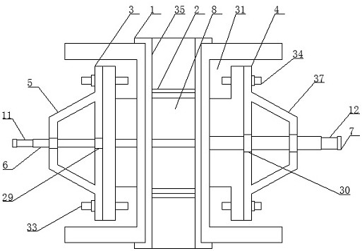
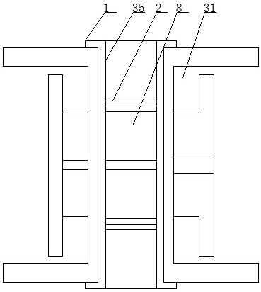
[0032] Such as Figure 1-8 As shown, the multi-seat valve with strong stability and easy adjustment according to the embodiment of the present invention includes a valve body 1 and a valve core 2 located in the valve body 1, and connecting seats are respectively provided on both sides of the valve body 1 One 3 and connecting seat two 4, the side of the connecting seat one 3 away from the connecting seat two 4 is provided with a connecting frame one 5, and the connecting frame one 5 is provided with a horizontally arranged shaft rod 6, the connecting The side of the seat two 4 away from the connecting seat one 3 is provided with a connecting frame two 37, and the connecting frame two 37 is provided with a rotating shaft 7 matched with it, and the rotating shaft 7 is close to the side of the connecting seat one 3 Extending into the valve body 1 and connecting with the valve core 2, the valve core 2 is provided with a flow channel 36, and the valve core 2 is provided with a seali...
Embodiment 2
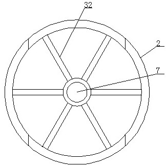
[0035] Such as Figure 1-8 As shown, the rotating shaft 7 is connected to the valve core 2 through a number of evenly distributed reinforcing ribs 32, and the joints of the shaft rod 6 and the rotating shaft 7 with the valve body 1 are provided with sealing rings, so The sealing ring is made of rubber, the connecting seat one 3 is connected with the valve body 1 through the connecting bolt one 33 , and the connecting seat two 4 is connected with the valve body 1 through the connecting bolt two 34 . Through the cooperative design of the first connecting bolt 33 and the second connecting bolt 34, it is convenient to install and disassemble the connecting seat one 3 and the second connecting seat 4.
Embodiment 3
[0037] Such as Figure 1-8 As shown, the handle 28 and the runner 14 are provided with matching non-slip rubber rings, the inner wall of the valve body 1 is provided with a rubber-lined sealing layer 35, and the rubber-lined sealing layer 35 extends On the connecting flange on the outside of the valve body 1 , the inner bottom wall of the flow passage 36 is inlaid with a sealed bearing, and the inner ring of the sealed bearing is connected with the shaft 6 .
PUM
 Abstract
Description
Claims
Application Information
 - R&D Engineer
- R&D Manager
- IP Professional
- Industry Leading Data Capabilities
- Powerful AI technology
- Patent DNA Extraction
Browse by: Latest US Patents, China's latest patents, Technical Efficacy Thesaurus, Application Domain, Technology Topic, Popular Technical Reports.
© 2024 PatSnap. All rights reserved.Legal|Privacy policy|Modern Slavery Act Transparency Statement|Sitemap|About US| Contact US: help@patsnap.com


