A pipe fitting routing support device

A technology for supporting devices and pipe fittings, applied in the directions of pipe supports, pipes/pipe joints/pipes, cable laying equipment, etc. Easy to observe and avoid the effect of sloping arrangement

Active Publication Date: 2022-04-01
HEBEI HONGYU COMM EQUIP
View PDF0 Cites 0 Cited by
  • Summary
  • Abstract
  • Description
  • Claims
  • Application Information

AI Technical Summary

Problems solved by technology

[0002] In the process of house decoration, the water level and potential will be changed, commonly known as changing water to electricity. In order to facilitate later maintenance and find the location of water and electricity damage in time when an accident occurs, it is necessary to disperse the water pipes and wires and pipes to various designated locations through the roof. During the construction process, the workers need to manually fix the water pipes and wire pipes on the roof, and then fix them with the fixing parts. Although the process is simple, the workers need to manually hold the pipes and hold their hands high for a long time. , causing pain in the arms of the workers, and at the same time, manual hand support will cause deviations in the position of the pipe fittings, which is not conducive to the concealed work of the pipe fittings in the later stage

Method used


Image

  • A pipe fitting routing support device
  • A pipe fitting routing support device
  • A pipe fitting routing support device

Examples


specific Embodiment approach 1

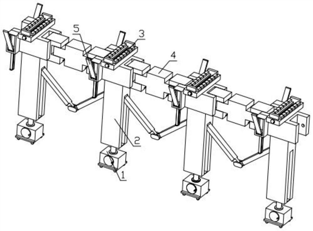
[0032] Combine below Figure 1-12 Describe this embodiment, a pipe fitting routing support device, including a bottom lifting mechanism 1, a connection and disassembly mechanism 2, a pipe fitting limit mechanism 3, an angle adjustment mechanism 4 and a wall locking mechanism 5, characterized in that: the bottom lifting mechanism Mechanism 1 is threadedly connected with connecting and dismounting mechanism 2, multiple connecting and dismounting mechanisms 2 are hingedly connected to each other, connecting and dismounting mechanism 2 is slidably installed in the groove provided on the angle adjustment mechanism 4, and the angle adjustment mechanism 4 is fixedly installed with a pipe limit mechanism 3. The two sides of the angle adjustment mechanism 4 are fixedly installed with a wall locking mechanism 5 .

specific Embodiment approach 2

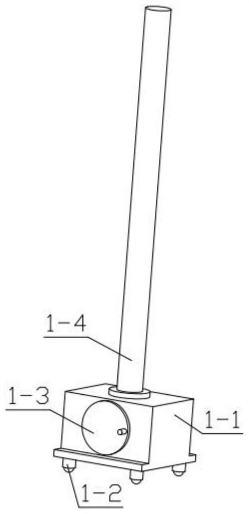
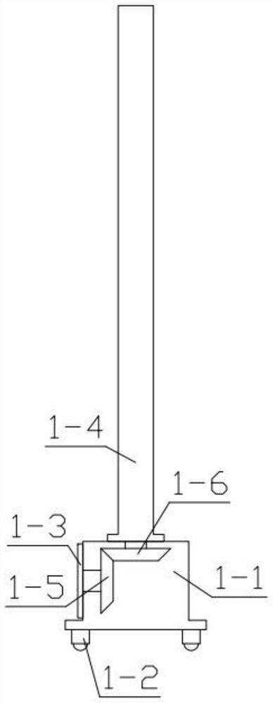
[0033] Combine below Figure 1-12 Describe this embodiment, this embodiment will further explain the first embodiment, the bottom lifting mechanism 1 includes a counterweight box 1-1, a universal wheel 1-2, a manual turntable 1-3, and a lifting threaded rod 1-4 , helical gear one 1-5, helical gear two 1-6, the bottom of the counterweight box 1-1 is fixedly equipped with universal wheels 1-2, and the groove of the counterweight box 1-1 is rotatably equipped with helical gears One 1-5, one side of the helical gear 1-5 passes through the counterweight box 1-1 and is fixedly installed with a manual turntable 1-3, and the second helical gear 1-6 is rotatably installed on the counterweight box 1-1 In the groove, helical gear one 1-5 is meshed with helical gear two 1-6, and helical gear two 1-6 is fixedly installed with lifting threaded rod 1-4.

specific Embodiment approach 3

[0034] Combine below Figure 1-12Describe this embodiment, this embodiment will further explain the second embodiment, the connection and detachment mechanism 2 includes a lifting block 2-1, a side rod 2-2, a side rod 2 2-3, and a hinge 2-4, The lifting block 2-1 is threadedly connected with the lifting threaded rod 1-4, a side bar 2-2 is hinged in the groove on one side of the lifting block 2-1, and the other end of the side bar 2-2 is hinged with a hinge 2- 4. The second side bar 2-3 is hinged in the groove on the other side of the lifting block 2-1, and the hinge 2-4 is hinged with the second side bar 2-3.


PUM


Abstract

The present invention relates to a device related to building materials, more specifically a pipe fitting routing support device, which includes a bottom lifting mechanism, a connection and disassembly mechanism, a pipe fitting limit mechanism, an angle adjustment mechanism and a wall locking mechanism. The bottom lifting mechanism and The connection and detachment mechanism is threaded, and multiple connection and detachment mechanisms are hingedly connected to each other. The connection and detachment mechanism is slidably installed in the groove provided on the angle adjustment mechanism. It is equipped with a wall locking mechanism; this device can ensure the position of the pipe fittings without deviation, and can adapt to pipe fittings of different diameters. The device can also position the pipe fittings at the corners to adapt to different shed shapes. The device is convenient for contraction and installation. Disassembles for easy transport.

Description

technical field [0001] The invention relates to a device related to building materials, in particular to a pipe fitting routing support device. Background technique [0002] In the process of house decoration, the water level and potential will be changed, commonly known as changing water to electricity. In order to facilitate later maintenance and find the location of water and electricity damage in time when an accident occurs, it is necessary to disperse the water pipes and wires and pipes to various designated locations through the roof. During the construction process, the workers need to manually fix the water pipes and wire pipes on the roof, and then fix them with the fixing parts. Although the process is simple, the workers need to manually hold the pipes and hold their hands high for a long time. , causing pain in the arms of the workers, and at the same time, manual hand support will cause deviations in the position of the pipe fittings, which is not conducive to ...

Claims


Application Information

Patent Timeline
Patent Type & Authority Patents(China)
IPC IPC(8): F16L3/02F16L3/205H02G1/06
CPCF16L3/02F16L3/2056H02G1/06
Inventor 孙海萍
Owner HEBEI HONGYU COMM EQUIP
Why Eureka
Try Eureka