Testing device and testing method for permeability of carbon fiber cloth in laying direction

A carbon fiber cloth and testing device technology, applied in the field of energy storage, can solve the problems of too many parts and complex assembly of the testing device

Active Publication Date: 2021-02-09
中海储能科技(北京)有限公司
View PDF8 Cites 0 Cited by
  • Summary
  • Abstract
  • Description
  • Claims
  • Application Information

AI Technical Summary

Problems solved by technology

[0004] Most of the tests on permeability in the prior art focus on the number of layers of the compressed fabric, the compression pressure or the permeability in the thickness direction, a

Method used


Image

  • Testing device and testing method for permeability of carbon fiber cloth in laying direction
  • Testing device and testing method for permeability of carbon fiber cloth in laying direction
  • Testing device and testing method for permeability of carbon fiber cloth in laying direction

Examples


Embodiment 1

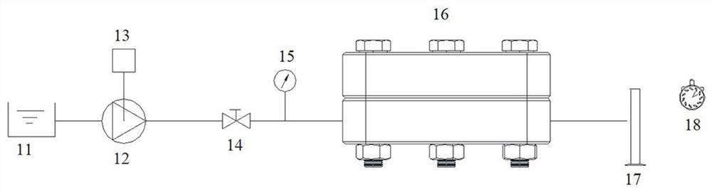
[0048]Such asfigure 1 As shown, a test device for the permeability of carbon fiber cloth in the direction of the ply includes a water tank 11, a frequency converter 13, a pump 12, a valve 14, a pressure gauge 15, a carbon fiber cloth fixture 16, a measuring cylinder and a timer 8.

[0049]The carbon fiber cloth clamp 16 has a water inlet and an outlet. The water tank 11 is connected to the water inlet through a pipeline. A pump 12 and a pressure gauge 15 are provided on the pipeline. The water outlet of the carbon fiber cloth clamp is connected to the water outlet. Mentioned measuring cylinder 17.

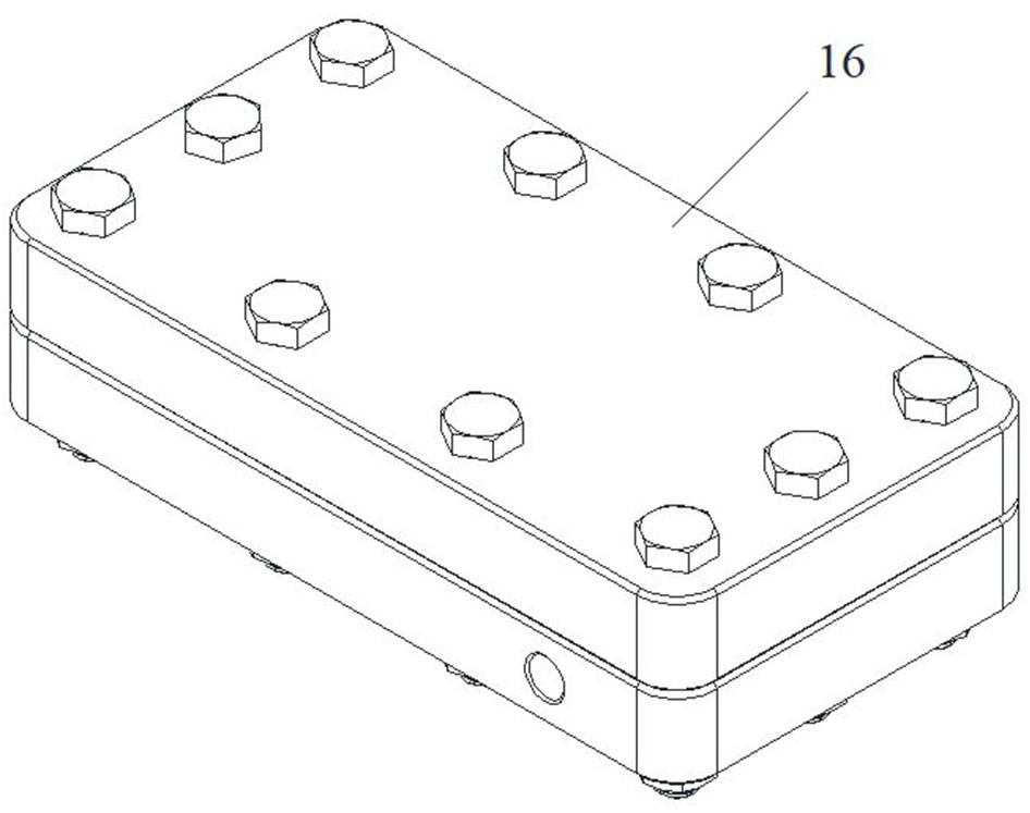
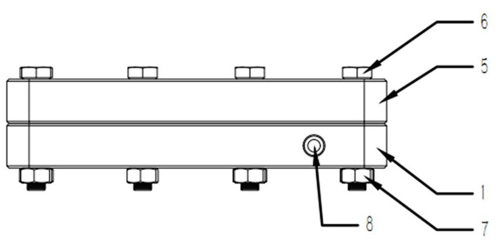
[0050]SeeFigure 2A ,Figure 2B ,image 3 The carbon fiber cloth fixture includes a cube-shaped upper fixture 5 and a lower fixture 1. The upper fixture 1 and the lower fixture 5 are fixed by bolts 6 and nuts 7; between the upper fixture 5 and the lower fixture 1 is the position for laying carbon fiber cloth, Two liquid inlet / outlet threaded holes 8 of the same size are opened on two opposite sid...

Embodiment 2

[0057]Using the device of Example 1, a method for testing the permeability of carbon fiber cloth in the direction of the ply, including operations:

[0058]Laying carbon fiber cloth and rectangular silica gel pad in the carbon fiber cloth fixture, fixing the upper and lower fixtures with bolts, and connecting pipelines;

[0059]Use a pump to send the fluid in the water tank into the carbon fiber cloth fixture, the fluid flows in from the inlet and out from the outlet, and the outflow measuring cylinder measures the volume, and the timing tool measures the time it takes to reach a certain volume in the measuring cylinder;

[0060]Use a pressure gauge to measure the fluid pressure at the inlet of the carbon fiber cloth fixture,

[0061]The inverter achieves the purpose of adjusting the water supply pressure of the fixture by controlling the frequency of the water pump, and the valve controls the on and off of the entire test flow path.

[0062]Turn on the water pump, adjust the frequency of the wate...


PUM

PropertyMeasurementUnit
Depthaaaaaaaaaa

Abstract

The invention provides a testing device and a testing method for permeability of carbon fiber cloth in a laying direction, the testing device comprises a water tank, a frequency converter, a pump, a valve, a pressure gauge, a carbon fiber cloth clamp, a measuring cylinder and a timing tool, the carbon fiber cloth clamp is provided with a water inlet and a water outlet, the water tank is connectedwith the water inlet through a pipeline, the pump and the pressure gauge are arranged on the pipeline, and the water outlet of the carbon fiber cloth clamp is connected with the measuring cylinder; and according to the method, the permeability of the carbon fiber cloth with the specific compression residual amount is achieved, and the permeability of the same carbon fiber cloth under different compression residual amounts and the permeability of different carbon fiber cloth under the same compression residual amount can be calculated. The carbon fiber cloth brand with the minimum permeabilityand the corresponding compression remaining amount are selected from the two variables of the carbon fiber cloth brand and the compression remaining amount to obtain the optimal battery performance.

Description

Technical field[0001]The invention belongs to the technical field of energy storage, and specifically relates to a test method for electrode materials of a flow battery.Background technique[0002]In the iron-chromium flow battery, carbon cloth is used as an electrode to provide an electrochemical reaction site, and electrons pass through the electrode and the ion membrane to form a potential difference, which can be charged and discharged. Under the cooperation of the bipolar plate and the plate frame, the electrolyte flows and diffuses in the direction of the carbon fiber cloth layer, and a chemical reaction occurs.[0003]The fit gap between the bipolar plate and the plate frame determines the remaining amount of compression of the carbon fiber cloth (thickness after compression), and different remaining amounts of compression correspond to different permeability. The smaller the remaining amount of compression, the smaller the permeability of the carbon fiber cloth, the greater the ...

Claims


Application Information

Patent Timeline
IPC IPC(8): G01N15/08
CPCG01N15/0806G01N15/0826
Inventor 不公告发明人
Owner 中海储能科技(北京)有限公司
Why Eureka
Try Eureka