A test device and test method for the permeability of carbon fiber cloth laying direction
What is AI technical title?
AI technical title is built by Patsnap AI team. It summarizes the technical point description of the patent document.
A carbon fiber cloth and testing device technology, applied in the field of energy storage, can solve the problems of complex assembly and too many parts of the testing device.
Active Publication Date: 2021-04-09
中海储能科技(北京)有限公司
View PDF8 Cites 0 Cited by
Summary
Abstract
Description
Claims
Application Information
AI Technical Summary
This helps you quickly interpret patents by identifying the three key elements:
Problems solved by technology
Method used
Benefits of technology
Problems solved by technology
[0004] Most of the tests on permeability in the prior art focus on the number of layers of the compressed fabric, the compression pressure or the permeability in the thickness direction, and the test device has too many parts and complex assembly [1-3] , there is no study on the permeability of carbon fiber cloth in the lay-up direction under a specific compression residual
Method used
Image
Click on the blue label to locate the original text in one second.
Reading with bidirectional positioning of images and text.
Examples
Embodiment 1
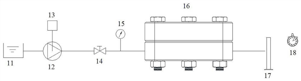
[0048] like figure 1 As shown, a test device for the permeability of carbon fiber cloth laying direction, including a water tank 11, a frequency converter 13, a pump 12, a valve 14, a pressure gauge 15, a carbon fiber cloth clamp 16, a measuring cylinder and a timer 8,
[0049] Described carbon fiber cloth fixture 16 has the inlet and outlet of water, and described water tank 11 is connected the inlet of water by pipeline, is provided with pump 12 and pressure gauge 15 on described pipeline, and the outlet of the water of described carbon fiber cloth fixture is connected The graduated cylinder 17 described above.
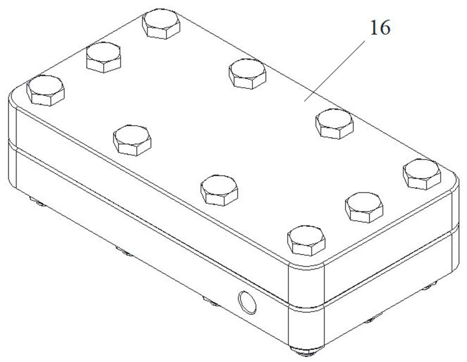
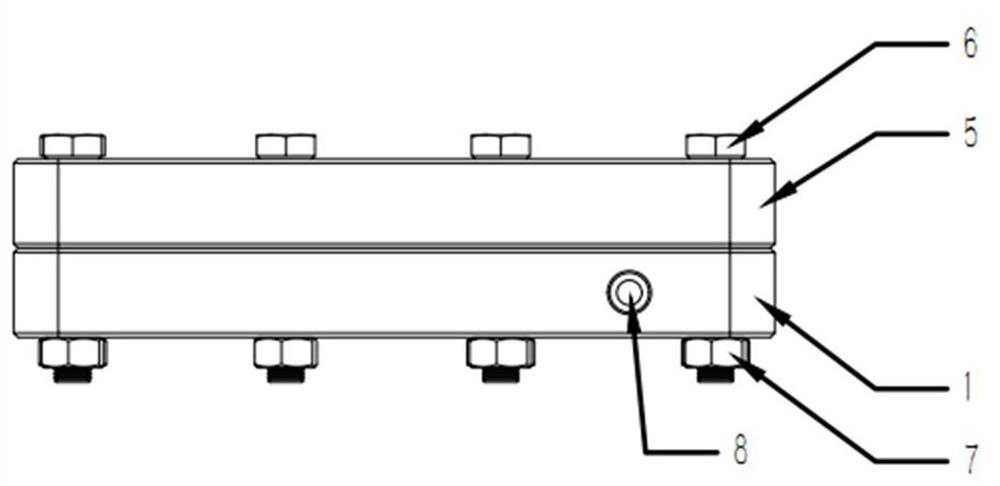
[0050] see Figure 2A , Figure 2B , image 3, the carbon fiber cloth clamp comprises a cube-shaped upper clamp 5 and a lower clamp 1, the upper clamp 1 and the lower clamp 5 are fixed with bolts 6 and nuts 7; between the upper clamp 5 and the lower clamp 1 is the position for laying carbon fiber cloth, and Two inlet / outlet threaded holes 8 of the same size are ...
Embodiment 2
[0057] Adopt the device of embodiment 1, a kind of test method of carbon fiber cloth ply direction permeability, comprises operation:
[0058] Lay carbon fiber cloth and rectangular silica gel pads in the carbon fiber cloth fixture, fix the upper and lower fixtures with bolts, and connect the pipelines;
[0059] Use a pump to send the fluid in the water tank into the carbon fiber cloth fixture. The fluid flows in from the inlet and flows out from the outlet. The amount of outflow is measured by a measuring cylinder, and the timing tool measures the time it takes for the measuring cylinder to reach a certain volume;
[0060] Measure the inlet fluid pressure of the carbon fiber cloth fixture with a pressure gauge,
[0061] The inverter controls the frequency of the water pump to adjust the water supply pressure of the fixture, and the valve controls the on-off of the entire test flow path.
[0062] Turn on the water pump, adjust the frequency of the water pump, open the valve, ...
PUM
Property
Measurement
Unit
depth
aaaaa
aaaaa
Abstract
The invention provides a test device and a test method for the permeability of carbon fiber cloth in the direction of layup. The test device includes a water tank, a frequency converter, a pump, a valve, a pressure gauge, a carbon fiber cloth fixture, a measuring cylinder and a timing tool. It has a water inlet and an outlet, the water tank is connected to the water inlet through a pipeline, a pump and a pressure gauge are arranged on the pipeline, and the water outlet of the carbon fiber cloth clamp is connected to the measuring cylinder; the invention solves the problem of specific The permeability of the carbon fiber cloth with the remaining amount of compression can be calculated. Among the two variables of carbon fiber cloth brand and compression residual amount, the carbon fiber cloth brand with the smallest permeability and its corresponding compressed residual amount are selected to obtain the best battery performance.
Description
technical field [0001] The invention belongs to the technical field of energy storage, and in particular relates to a method for testing electrode materials of a liquid flow battery. Background technique [0002] In the iron-chromiumflow battery, the carbon cloth is used as an electrode to provide an electrochemical reaction site, and the electrons pass through the electrode and the ion membrane to form a potential difference to be charged and discharged. With the cooperation of the bipolar plate and the plate frame, the electrolyte flows and diffuses in the direction of the carbon fiber cloth layer, and a chemical reaction occurs. [0003] The fit gap between the bipolar plate and the plate frame determines the compression residual (thickness after compression) of the carbon fiber cloth, and different compression residuals correspond to different permeability. The smaller the residual amount of compression, the smaller the permeability of the carbon fiber cloth, the great...
Claims
Application Information
Patent Timeline
Application Date:The date an application was filed.
Publication Date:The date a patent or application was officially published.
First Publication Date:The earliest publication date of a patent with the same application number.
Issue Date:Publication date of the patent grant document.
PCT Entry Date:The Entry date of PCT National Phase.
Estimated Expiry Date:The statutory expiry date of a patent right according to the Patent Law, and it is the longest term of protection that the patent right can achieve without the termination of the patent right due to other reasons(Term extension factor has been taken into account ).
Invalid Date:Actual expiry date is based on effective date or publication date of legal transaction data of invalid patent.

