Obstacle trajectory prediction method and device

A trajectory prediction and obstacle technology, applied in the computer field, can solve the problems of poor trajectory accuracy of obstacles, failure to describe obstacle interaction, etc., and achieve the effect of high trajectory accuracy

Pending Publication Date: 2021-02-09
BEIJING SANKUAI ONLINE TECH CO LTD
View PDF4 Cites 9 Cited by
  • Summary
  • Abstract
  • Description
  • Claims
  • Application Information

AI Technical Summary

Problems solved by technology

But in the real world, when each obstacle considers how to drive in the future, it not only considers itself (for example, how to reach the destination in the shortest distance), but also considers avoiding other obstacles, that is, the d

Method used


Image

  • Obstacle trajectory prediction method and device
  • Obstacle trajectory prediction method and device
  • Obstacle trajectory prediction method and device

Examples


Embodiment 1

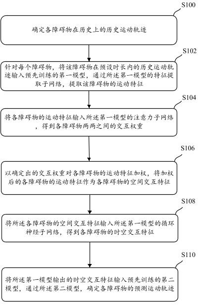
[0084] figure 1 It is a schematic flow chart of an obstacle trajectory prediction method in this manual, which specifically includes the following steps:

[0085] S100: Determine the historical movement track of each obstacle in history.

[0086] The trajectory prediction method provided in this manual can be executed by unmanned equipment (hereinafter referred to as unmanned vehicle), or by electronic equipment that can transmit information with unmanned vehicles or control unmanned vehicles, such as notebooks Computers, mobile phones, servers, etc., this manual does not limit them. For the convenience of description, this specification takes the unmanned vehicle as the execution subject, and exemplifies the trajectory prediction method provided in this specification.

[0087] The unmanned vehicles described in this specification may include self-driving vehicles and vehicles with assisted driving functions. Unmanned vehicles can be delivery vehicles used in the distributi...

Embodiment 2

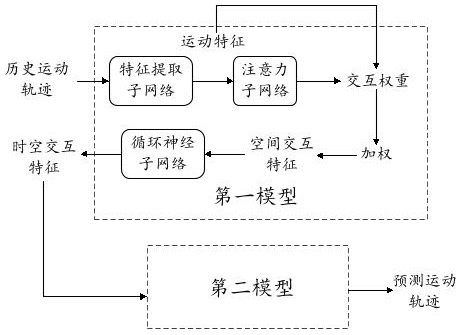
[0123] Figure 7 The training provided for the embodiment of this specification is as follows: figure 2 The schematic flow chart of the first model and the second model shown, including:

[0124] S700: Determine each sample obstacle and a sample trajectory corresponding to each sample obstacle.

[0125] S702: According to the preset reference time, for each sample obstacle, among the sample trajectories corresponding to the sample obstacle, the trajectory before the reference time is taken as the initial trajectory of the sample obstacle, and at the reference time The final trajectory is used as the labeled trajectory of the sample obstacle.

[0126] Generally speaking, the sample trajectory is the historical real trajectory of each obstacle collected in advance. Specifically, sensing equipment can be arranged in the real environment in advance, and the collected obstacles can be selected as sample obstacles, and the collected The real trajectories of the obtained sample o...


PUM


Abstract

The invention provides an obstacle trajectory prediction method and device, and the method comprises the steps: the interaction weight between every two obstacles is determined according to the motionfeatures extracted from the historical motion trajectory of each obstacle, the corresponding motion features are weighted through the determined interaction weights, and weighted spatial interactionfeatures are obtained; and a recurrent neural sub-network obtains the space-time interaction feature of each obstacle according to the input spatial interaction features, and a pre-trained second model determines the predicted motion trail of each obstacle according to the space-time interaction features of each obstacle, wherein the interaction weight reflects the influence degree between each obstacle and each other obstacle. Therefore, the spatial interaction features describe the interaction between the obstacles on the basis of the motion features, and the predicted future trajectory precision of the obstacles is higher.

Description

technical field [0001] This description relates to the field of computer technology, in particular to a method and device for trajectory prediction of obstacles. Background technique [0002] At present, in the field of unmanned driving technology, a reference trajectory for a period of time in the future is usually planned for the unmanned equipment, so that the unmanned equipment can travel along the reference trajectory. [0003] Due to the existence of obstacles on the road, the reference trajectory planned for the unmanned equipment needs to ensure that the unmanned equipment can avoid obstacles. For obstacles that can participate in traffic and whose position will change over time, in order for unmanned driving equipment to avoid them accurately, it is usually necessary to predict the future trajectory of the obstacle. [0004] In the prior art, the future trajectory of each obstacle is often predicted only according to the historical state information of each obstacl...

Claims


Application Information

Patent Timeline
IPC IPC(8): G06Q10/04G06N3/04
CPCG06Q10/04G06N3/044G06N3/045
Inventor 徐一樊明宇任冬淳夏华夏代亚暄钱德恒朱炎亮
Owner BEIJING SANKUAI ONLINE TECH CO LTD
Why Eureka
Try Eureka