Ultra-wideband antenna

An ultra-wideband antenna and antenna body technology, which is applied to antennas, antenna grounding devices, and devices that enable antennas to work in different bands at the same time, can solve the problem that the impedance of UWB antennas is not very good, and the antenna gain and efficiency cannot meet the needs of users and other issues, to achieve the effect of good impedance characteristics, high gain characteristics, and enhanced radiation field strength

Pending Publication Date: 2021-02-09
深圳市飞敏科技有限公司
View PDF0 Cites 3 Cited by
  • Summary
  • Abstract
  • Description
  • Claims
  • Application Information

AI Technical Summary

Problems solved by technology

[0002] The impedance of the current UWB antenna is not very good, and the gain and efficiency of the antenna cannot meet the needs of users, and it is urgent to solve

Method used


Image

  • Ultra-wideband antenna
  • Ultra-wideband antenna
  • Ultra-wideband antenna

Examples


Embodiment Construction

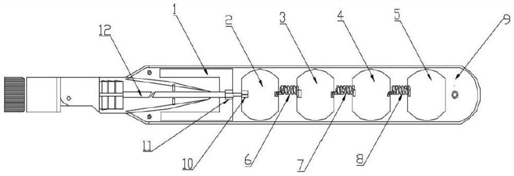
[0018] like figure 1 As shown, the present invention discloses an ultra-wideband antenna, including a housing 9, and an antenna body installed in the housing 9. The antenna body includes a ground plate 1, a radiation element, a spiral impedance transformation line, and a coaxial line 12 , there are multiple radiating units, the coaxial line 12 is provided with an outer conductor 11 and a shielding layer inner conductor 10, two adjacent radiating units are connected through the spiral impedance transformation line, the outer The conductor 11 is connected to the ground plate 1 , and the conductor 10 in the shielding layer is connected to the radiation unit.

[0019] There are four radiating units, the four radiating units are respectively the first radiating unit 2, the second radiating unit 3, the third radiating unit 4, and the fourth radiating unit 5, and the number of the spiral impedance transformation lines is three, The three spiral impedance transformation lines are res...


PUM


Abstract

The invention provides an ultra-wideband antenna, and the antenna comprises a shell and an antenna main body installed in the shell; the antenna main body comprises a grounding plate, a plurality of radiation units, a spiral impedance conversion line and a coaxial line, wherein the coaxial line is provided with an outer conductor and a shielding layer inner conductor; every two adjacent radiationunits are connected through the spiral impedance conversion line, the outer conductor is connected with the grounding plate, and the shielding layer inner conductor is connected with the radiation units. The invention has the beneficial effects that the ultra wide band antenna achieves good impedance characteristics in the frequency band of 2GHz and 7GHz, the whole radiation field intensity of theantenna is enhanced, and therefore the high gain characteristic of the antenna is achieved.

Description

technical field [0001] The invention relates to the technical field of antennas, in particular to an ultra-wideband antenna. Background technique [0002] The impedance of the current UWB antenna is not very good, and the gain and efficiency of the antenna cannot meet the needs of users, and urgently need to be solved. Contents of the invention [0003] The invention provides an ultra-wideband antenna, which includes a housing and an antenna body installed in the housing. The antenna body includes a ground plate, a radiation unit, a spiral impedance transformation line, and a coaxial line. The radiation unit is a plurality of One, the coaxial line is provided with an outer conductor and a shielding layer inner conductor, and two adjacent radiation units are connected through the spiral impedance transformation line, the outer conductor is connected to the ground plate, and the The inner conductor of the shielding layer is connected to the radiation unit. [0004] As a fu...

Claims


Application Information

Patent Timeline
Patent Type & Authority Applications(China)
IPC IPC(8): H01Q5/25H01Q1/36H01Q1/48
CPCH01Q1/36H01Q1/48H01Q5/25
Inventor 夏兴喜
Owner 深圳市飞敏科技有限公司
Why Eureka
Try Eureka