Track and field runway line drawing machine
A line drawing machine and track technology, applied in the field of sports, can solve the problem that the track and field track cannot be drawn temporarily.
- Summary
- Abstract
- Description
- Claims
- Application Information
AI Technical Summary
Benefits of technology
Problems solved by technology
Method used
Image
Examples
specific Embodiment approach 1
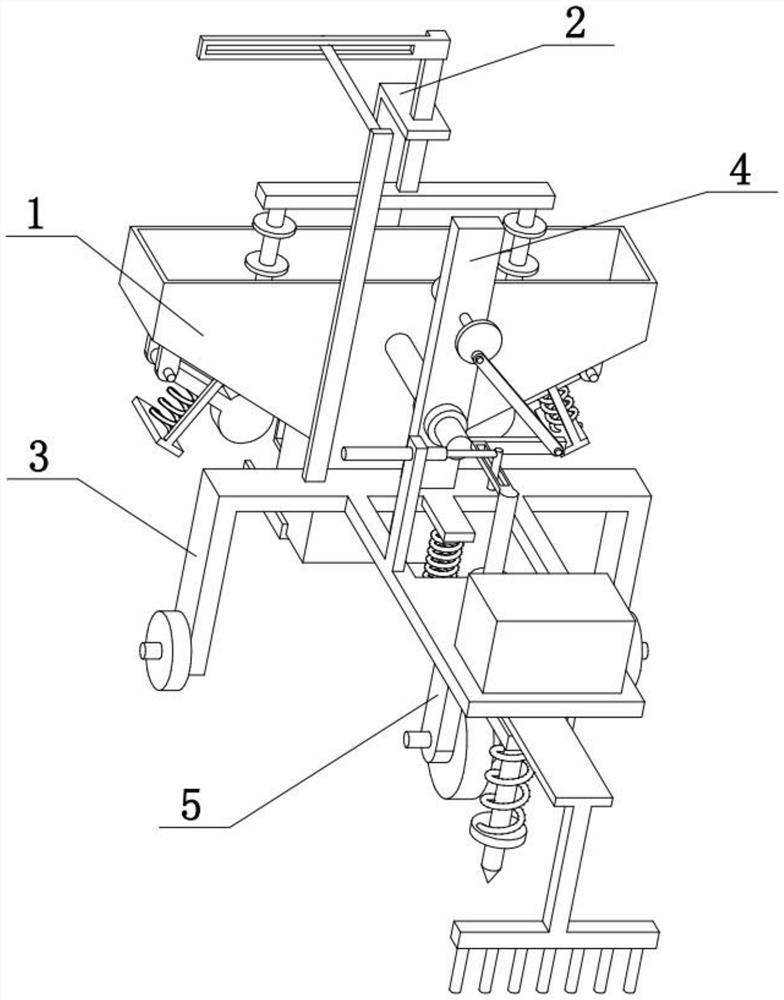
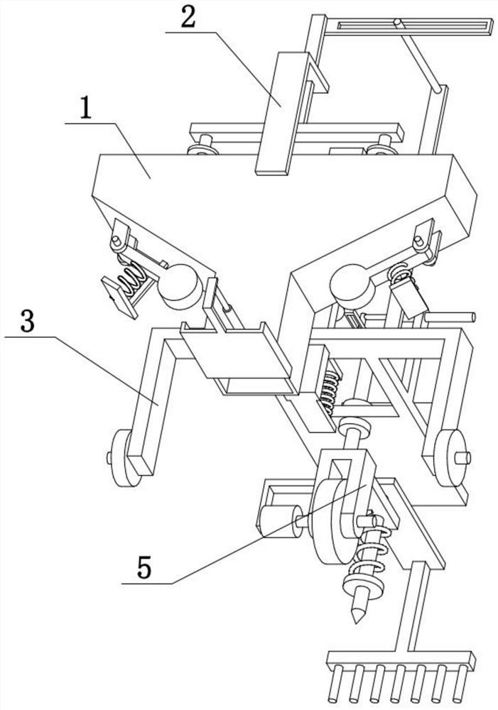
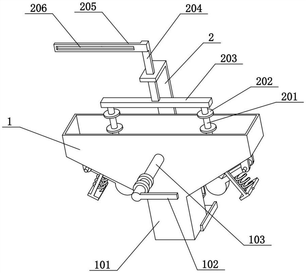
[0027] Combine below Figure 1-8 Describe this embodiment, the present invention relates to the field of sports, more specifically a track and field track line drawing machine, including a storage box 1, a discharge barrel 101, a bottom cover 104, an oil cylinder I105, a hammer head 106, a spring frame 107 and a hammer Bar 108, the present invention can temporarily draw track and field track.
[0028] The storage box 1 is wide at the top and narrow at the bottom. The bottom of the storage box 1 is provided with a discharge cylinder 101. The rear side of the discharge cylinder 101 is fixedly connected with an oil cylinder I105. The bottom cover 104 is slidingly connected to the bottom of the discharge cylinder 101. The oil cylinder I105 The rear end of the bottom cover 104 is fixedly connected to the rear of the bottom cover 104. There is one hammer rod 108 on the left and right sides. The left and right sides of the storage box 1 are inclined surfaces. The inner ends of the t...
specific Embodiment approach 2
[0030] Combine below Figure 1-8 Illustrate this embodiment, described track and field runway line drawing machine also comprises L-shaped frame 2, vertical column 201, disc 202, horizontal bar 203 and lifting column 204, the upper part of storage box 1 is fixedly connected with L-shaped frame 2, L-shaped The upper part of the frame 2 is vertically slidably connected with a lifting column 204, and the lower end of the lifting column 204 is fixedly connected with a horizontal bar 203, and the left and right ends of the lower side of the horizontal bar 203 are fixedly connected with vertical columns 201, and each vertical column 201 is connected from the top to the top. A plurality of discs 202 are fixedly connected to the bottom, and two vertical columns 201 are respectively located above the two storage boxes 1 . The lifting column 204 can slide vertically on the L-shaped frame 2 to drive the horizontal bar 203, the two vertical columns 201 and the plurality of discs 202 on th...
specific Embodiment approach 3
[0032] Combine below Figure 1-8To illustrate this embodiment, the track and field line drawing machine also includes a circumferential rod 102, a fixed shaft 103, a rectangular column 4, a disc 401 and a hinged rod 402, and the front side of the storage box 1 is fixedly connected with a fixed shaft 103, and the fixed shaft 103 The front end of the shaft is fixedly connected with a circumferential rod 102, and the front end of the fixed shaft 103 is rotatably connected to the middle part of the rectangular column 4. The upper part of the rectangular column 4 is provided with a disc 401 driven by a motor, and the eccentric position of the disc 401 is hinged with a hinged rod 402. The lower end of the hinged rod 402 is hinged on the outer end of the circumferential rod 102 . When the disk 401 rotates, the hinge rod 402 drives the circumferential rod 102 to swing up and down, and then drives the fixed shaft 103 to rotate forward and reverse on the rectangular column 4, and then d...
PUM
 Abstract
Description
Claims
Application Information
 - R&D
- Intellectual Property
- Life Sciences
- Materials
- Tech Scout
- Unparalleled Data Quality
- Higher Quality Content
- 60% Fewer Hallucinations
Browse by: Latest US Patents, China's latest patents, Technical Efficacy Thesaurus, Application Domain, Technology Topic, Popular Technical Reports.
© 2025 PatSnap. All rights reserved.Legal|Privacy policy|Modern Slavery Act Transparency Statement|Sitemap|About US| Contact US: help@patsnap.com


