Automatic steel sheet bending device

An automatic, steel sheet technology, applied in the direction of metal processing equipment, forming tools, feeding devices, etc., can solve the problems of inconvenient operation, low production efficiency, high production cost, etc., and achieve the effect of reducing manual participation

Active Publication Date: 2021-02-12
苏州卯是卯自动化设备有限公司
7 Cites 0 Cited by

AI-Extracted Technical Summary

Problems solved by technology

This method of operation increases the labor intensity of workers and reduces production efficiency.
At the same time, the bending machine has a large volume and is inconvenient to operate. When processing small batches of parts, the production cost is high and the efficiency is low.
Moreover, there are still great potential safety hazards when manually operating the bending machine.
With the improvement of ...

Abstract

The invention relates to the technical field of metal bending devices, and particularly relates to an automatic steel sheet bending device. The automatic steel sheet bending device comprises a machinebody, a feeding mechanism, a conveying mechanism, a bending mechanism and a material collecting groove, wherein the bending mechanism is arranged in the machine body and comprises an upper cutting die mechanism and a lower die assembly mechanism; the lower die assembly mechanism comprises a mounting table, a fixed die, a movable die and a die locking mechanism; the die locking mechanism drives the movable die to be opened or locked; the mounting table is provided with a material falling opening; the material falling opening is formed below a die cavity; and in the die locking state, the movable die seals the material falling opening, after bending is completed, an upper cutting die is lifted up, the movable die is driven by the die locking mechanism to get away from the fixed die, the material falling opening below is exposed, and a bent workpiece falls into the material collecting groove below the material falling opening to be collected. The automatic steel sheet bending device canautomatically complete the functions of workpiece feeding, supplying, bending and discharging collecting, and manpower is reduced.

Application Domain

Technology Topic

Image

  • Automatic steel sheet bending device
  • Automatic steel sheet bending device
  • Automatic steel sheet bending device

Examples

  • Experimental program(1)

Example Embodiment

[0025]The technical solutions in the embodiments of the present invention will be described clearly and completely below. Obviously, the described embodiments are only a part of the embodiments of the present invention, rather than all the embodiments. Based on the embodiments of the present invention, all other embodiments obtained by those of ordinary skill in the art without creative work shall fall within the protection scope of the present invention.
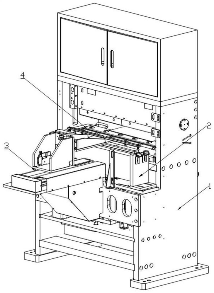
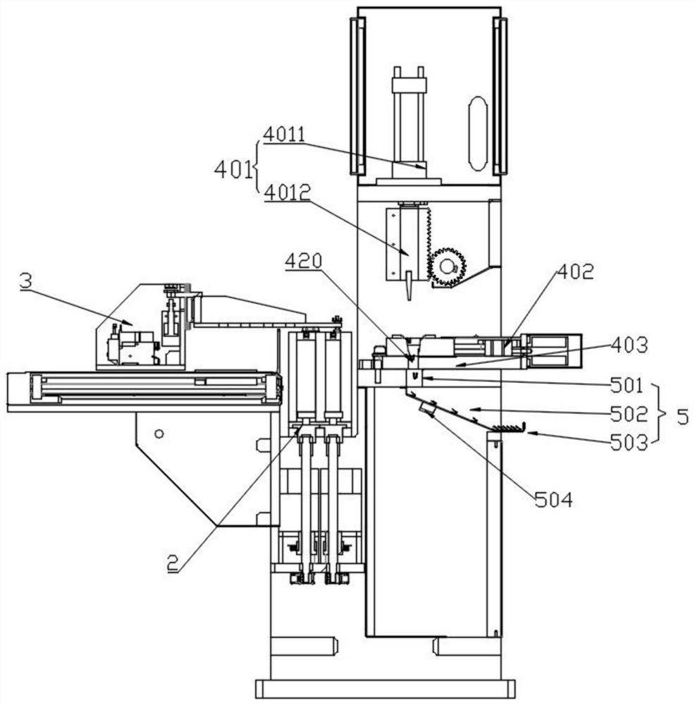
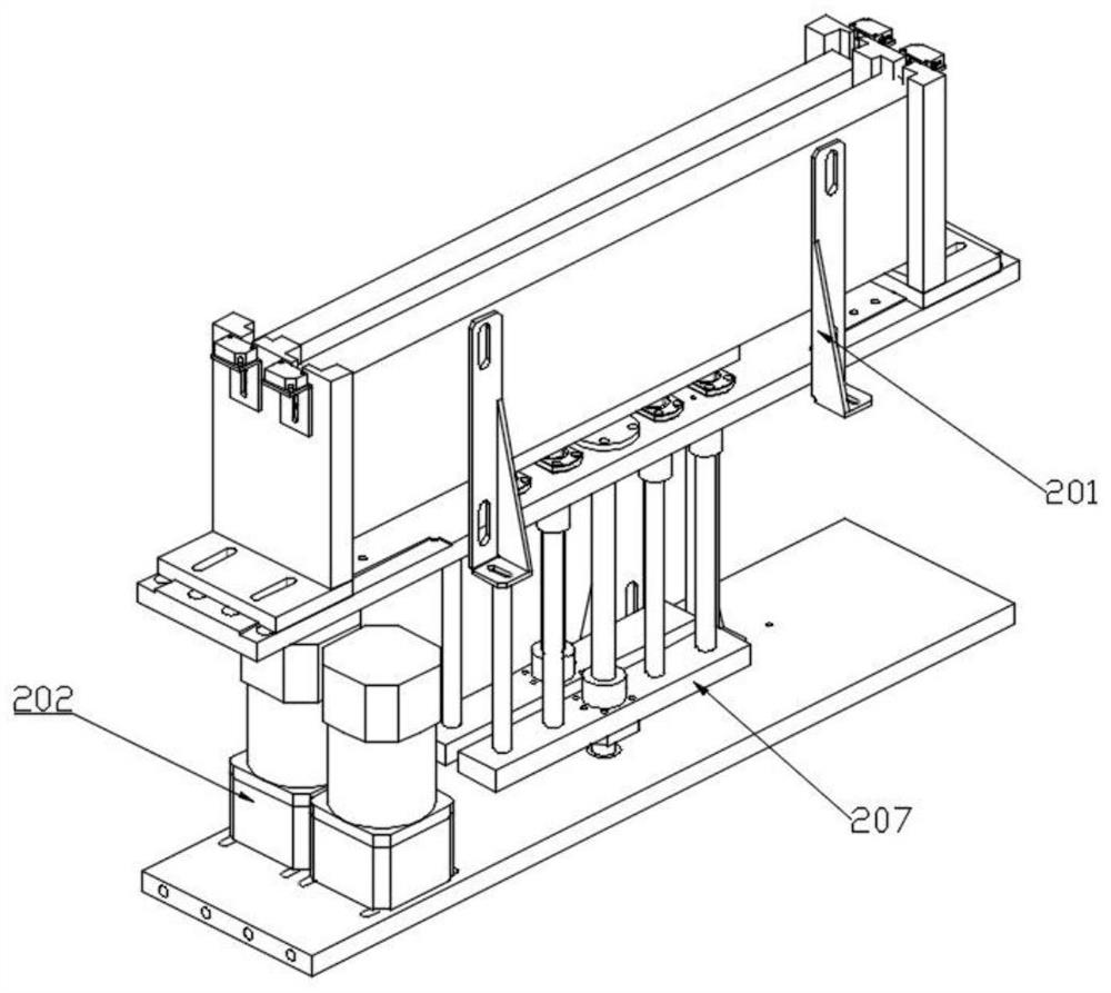
[0026]Such asFigure 1-8 As shown, an automatic steel sheet bending equipment in this embodiment includes a body 1, a feeding mechanism 2, a feeding mechanism 3, a bending mechanism 4, and a collecting trough 5. The feeding mechanism 2 is arranged in the The front end of the body 1 is used to carry and deliver workpieces; the feeding mechanism 3 is arranged above the feeding mechanism 2 and has a movement mechanism and a workpiece suction mechanism 305; the bending mechanism 4 is arranged in the body 1 , Including an upper knife mold mechanism 401 and a lower mold clamping mechanism 402. The upper knife mold mechanism 401 includes a lower pressing device 4011 arranged above the body 1 and an upper knife mold 4012 arranged on the lower pressing end of the lower pressing device 4011. In the example, the lower pressing device 4011 adopts an oil cylinder. In other embodiments, other technical solutions can be used, which are not required here. The lower mold clamping mechanism 402 is arranged below the upper die mechanism 401, and the lower mold The clamping mechanism 402 includes a mounting table 403, a fixed mold 404, a movable mold 405, and a mold clamping mechanism 406. The clamping mechanism 406 drives the movable mold 405 to open or lock the mold. The fixed mold 404 and the movable mold 405 are both Set on the mounting table 403, when the mold is locked, the fixed mold 404 and the movable mold 405 are close to each other to form a mold cavity. The upper part of the mold cavity has an opening for the upper knife mold 4012 to enter. The fixed mold 404 and the movable mold 405 is provided with a workpiece positioning tool 419 at the opening. The feeding mechanism 3 transfers the workpiece to the workpiece positioning tool 419. In the clamping state, the lowering device 4011 drives the upper die 4012 to descend, and the sheet-shaped workpiece Press into the mold cavity to complete the bending. At this time, the movable mold 405 is in a locked state; the mounting platform 403 is provided with a blanking port 420, which is set under the mold cavity, and is in a locked state , The movable mold 405 closes the blanking port 420. After the bending is completed, the upper die 4012 is lifted up, and the movable mold 405 is driven by the clamping mechanism 406 to move away from the fixed mold 404, exposing the lower blanking port 420, bending The workpiece falls into the collecting trough 5 below the blanking port 420 to complete collection.
[0027]Such asFigure 3-4As shown, in this embodiment, the loading mechanism 2 includes a loading tool 201 and a jacking device. The loading tool 201 is provided on the body 1, and the loading tool 201 has a workpiece containing cavity. The workpiece to be bent is placed in the workpiece accommodating cavity. The lifting device includes a lifting motor 202, a lifting screw 203, and a lifting plate 204 arranged on the lifting screw 203 through a nut. The lifting motor 202 is passed through a timing belt. 205 drives the lifting screw 203 to rotate, the lifting plate 204 is provided with a plurality of lifting columns 206, the lifting columns 206 penetrate the bottom of the loading tool 201 and extend into the workpiece accommodating cavity. The top of the lifting column 206 is provided with a lifting plate 207, and the workpiece is lifted on the lifting plate 207. When the lifting motor 202 rotates, the lifting screw 203 is driven to rotate by the timing belt 205, thereby driving the lifting plate 204 to rise and lift the workpiece upward The lifted workpiece is fed into the bending mechanism 4 by the feeding mechanism 3.
[0028]Such asFigure 5 As shown, in this embodiment, the feeding mechanism 3 is set on the body 1 through a mounting base 301, and the movement mechanism includes a timing belt sliding table 302 fixed on the mounting base 301 and a timing belt sliding table 302. The lifting and reclaiming mechanism includes a reclaiming arm 303 and a lifting drive device 304. The rear end of the reclaiming arm 303 is slidably connected to the timing belt slide 302 through a guide rail, and the lifting drive The moving end of the device 304 is connected to the reclaiming arm 303 through a connecting block, and the workpiece suction mechanism 305 is provided at the front end of the reclaiming arm 303. Specifically, the workpiece suction mechanism 305 may be a cross bar with a suction cup, which is driven by the timing belt sliding table 302 to reciprocate between the workpiece positioning tool 419 and the workpiece receiving cavity to complete the transfer of the workpiece.
[0029]In this embodiment, the clamping mechanism 406 is asFigure 6 As shown, it includes a slide plate 408 slidably mounted on the mounting platform 403 through a slide plate guide rail 407, a slide plate driving device 409, and a toggle mechanism 410 provided on both sides of the slide plate 408. The toggle mechanism 410 includes an angle bracket 411 , The first connecting rod 412 and the second connecting rod 413, the angle bracket 411 has a first hinge point 414, a second hinge point 415 and a third hinge point 416, wherein the first hinge point 414 at the bottom through a fixed pin It is hinged to the mounting platform 403. The two ends of the first link 412 are hinged to the sliding plate 408 and the second hinge point 415 respectively. The two ends of the second link 413 are hinged to the third hinge point 416 and the movable mold 405 The side. The specific movement mode of the clamping mechanism 406 is: in the mold opening state (Figure 7 ), the movable mold 405 and the fixed mold 404 are far away from each other, the sliding plate 408 is in a position far from the movable mold 405, the first connecting rod 412 pulls the angle bracket 411 to rotate a certain angle, so that the first hinge point 414 and the third hinge point 416 between The connecting line and the second connecting rod 413 have a small included angle (for the convenience of the following description, the included angle is named α); when clamping (Figure 8 ), the sliding plate 408 moves in the direction of the sliding plate guide rail 407 toward the movable mold 405, and the angle bracket 411 rotates outward under the push of the first connecting rod 412, so that α becomes larger, so that the second connecting rod 413 pushes the movable mold 405 Move in the direction of the fixed mold 404, and finally the movable mold 405 and the fixed mold 404 abut against each other. Preferably, when the movable mold 405 and the fixed mold 404 collide, α is 180°. At this time, the angle bracket 411 and the second connecting rod 413 are shared The movable mold 405 is pressed against the fixed mold 404, and the mold clamping is firmer. The two toggle link mechanisms 410 are set to act on the two ends of the movable mold 405 respectively. They have the advantages of uniform force, stable mold opening speed, stable mold clamping force, and low power required. The distance between the two toggle mechanisms 410 It depends more on the length of the two first connecting rods 412. Therefore, by providing a longer-length first connecting rod 412, a longer-length movable mold 405 can be smoothly locked.
[0030]In order to ensure the smooth movement of the movable mold 405, the mounting platform 403 is also provided with a movable mold guide rail 417, the movable mold 405 is slidingly fitted with the movable mold guide rail 417, and the mounting table 403 is mounted on the movable mold 405 Both ends are also provided with mold positioning blocks 418, the mold positioning blocks 418 are provided with an embedded groove, and both ends of the movable mold 405 are provided with embedded blocks, and the embedded blocks are slidably embedded in the embedded grooves.
[0031]In this embodiment, the collecting tank 5 includes a connected vertical section 501, an inclined section 502, and a collecting table 503, and a full material sensing device 504 is provided on the inclined section 502. The full-material sensing device 504 may be a laser sensing device. When a workpiece stays in the inclined section 502 for a long time, it can be determined that the collecting tank 5 is full.
[0032]Finally, it should be noted that the above embodiments are only used to illustrate the technical solutions of the present invention and not to limit them. Although the present invention has been described in detail with reference to the preferred embodiments, those of ordinary skill in the art should understand that the technical solutions of the present invention can be implemented Modifications or equivalent replacements without departing from the purpose and scope of the technical solution of the present invention should be covered by the scope of the claims of the present invention.

PUM

no PUM

Description & Claims & Application Information

We can also present the details of the Description, Claims and Application information to help users get a comprehensive understanding of the technical details of the patent, such as background art, summary of invention, brief description of drawings, description of embodiments, and other original content. On the other hand, users can also determine the specific scope of protection of the technology through the list of claims; as well as understand the changes in the life cycle of the technology with the presentation of the patent timeline. Login to view more.

Similar technology patents

Classification and recommendation of technical efficacy words

Why Eureka
Try Eureka