Eureka AIR delivers breakthrough ideas for toughest innovation challenges, trusted by R&D personnel around the world.

Reservoir dam deformation monitoring method and system

A technology for deformation monitoring and dam body, which is applied in the direction of measuring devices, instruments, optical devices, etc., can solve the problems of limited installation conditions, high installation costs, and large influence of geographical environment, so as to improve measurement accuracy, reduce monitoring costs, and improve accuracy. high effect

Inactive Publication Date: 2017-04-26
UNIV OF JINAN
View PDF6 Cites 16 Cited by
  • Summary
  • Abstract
  • Description
  • Claims
  • Application Information

AI Technical Summary

Problems solved by technology

[0008] 2. Install or bury some displacement monitoring instruments on the surface of the dam body, usually only can measure single item displacement data (horizontal displacement or vertical displacement) of the measuring point
The internal displacement monitoring of the dam body can only use traditional single-item displacement monitoring equipment, which needs to be pre-buried or drilled for installation, which is inconvenient for construction, and there is no good alternative method at present; the three-dimensional data monitoring equipment used for the surface displacement of the dam body is easy to install and has high performance. Stable and high precision, but greatly affected by the geographical environment, the installation conditions are limited, and the localization rate of such equipment is low and the installation cost is high

Method used


Image

  • Reservoir dam deformation monitoring method and system
  • Reservoir dam deformation monitoring method and system
  • Reservoir dam deformation monitoring method and system

Examples


Embodiment Construction

[0062] The following disclosure provides many different embodiments or examples for implementing different structures of the present invention. To simplify the disclosure of the present invention, components and arrangements of specific examples are described below. Furthermore, the present invention may repeat reference numerals and / or letters in different instances. This repetition is for the purpose of simplicity and clarity and does not in itself indicate a relationship between the various embodiments and / or arrangements discussed. It should be noted that components illustrated in the figures are not necessarily drawn to scale. Descriptions of well-known components and processing techniques and processes are omitted herein to avoid unnecessarily limiting the present invention.

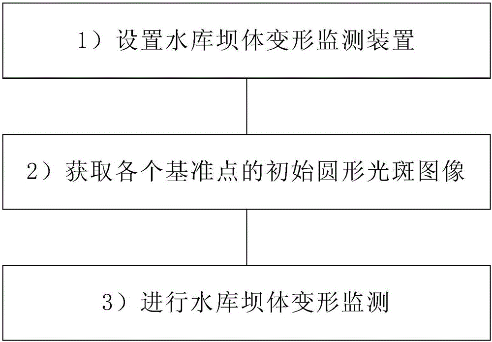
[0063] Such as figure 1 Shown, a kind of reservoir dam deformation monitoring method of the present invention, it comprises following process:

[0064] 1) Install reservoir dam deformation moni...


PUM


Abstract

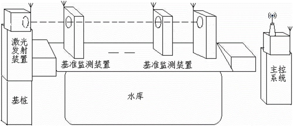
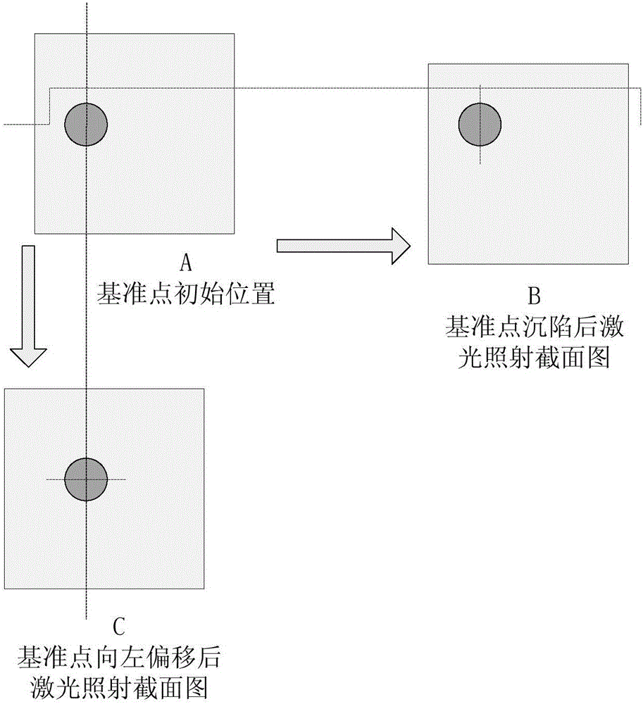
The invention relates to a reservoir dam deformation monitoring method and system. The monitoring method includes the following steps that: 1) a reservoir dam deformation monitoring device is set; 2) the initial circular light spot images of each reference point are obtained; and 3) reservoir dam deformation monitoring is carried out. The reservoir dam deformation monitoring system includes a laser emitting device, reference point detecting devices and a main control system; the laser emitting device is arranged at one end of a dam and is used for emitting collimating laser light adopted as a reference line; a plurality of reference points with equal intervals are arranged one a ray with the laser emitting device adopted as an end point; one reference point detecting device is arranged at each reference point; the reference point detecting devices are used for detecting the subsidence and horizontal displacement of the dam; and the main control system is connected with the laser emitting device and the reference point detecting devices through a wireless communication mode and is used for transmitting detection commands, receiving detected data and performing analysis processing on the detected data. With the reservoir dam deformation monitoring method and system of the invention adopted, the automatic detection of the subsidence and horizontal displacement of the dam can be realized, the measurement accuracy of the reservoir dam is improved, and monitoring costs can be reduced.

Description

technical field [0001] The invention relates to a reservoir dam body monitoring method and device, in particular to a reservoir dam body deformation monitoring method and system. Background technique [0002] Reservoir dams are common engineering projects in water conservancy construction. After concrete dams and masonry dams are built and used for water storage, they will inevitably be deformed under the action of water, sediment, waves, uplift pressure, temperature, and earthquakes, which will seriously lead to subsidence. , the cases are numerous. Therefore, dam safety monitoring technology is an international concern. [0003] The dam structural safety monitoring system involves multiple disciplines such as optics, sensors, and electronics, and its development has gone through two stages: [0004] 1. Observation stage (1891-1964), also known as prototype observation. Because the monitoring level at this stage is relatively low, it is only manual observation and monito...

Claims


Application Information

Patent Timeline
Patent Type & Authority Applications(China)
IPC IPC(8): G01B11/16
CPCG01B11/16
Inventor 孟凡民李聪
Owner UNIV OF JINAN
Why Eureka
Eureka Blog
Learn More