

Fairing inclined pushing axial separation device
A technology of axial separation and fairing, which is applied in the docking device of aerospace vehicles, transportation and packaging, space navigation equipment, etc., can solve the problems of insufficient vertical installation of the separation mechanism and occupation of the envelope space of the fairing, and achieve the goal of packaging The effect of small network space
- Summary
- Abstract
- Description
- Claims
- Application Information
AI Technical Summary
Problems solved by technology
Method used
Image

Examples
Embodiment 1
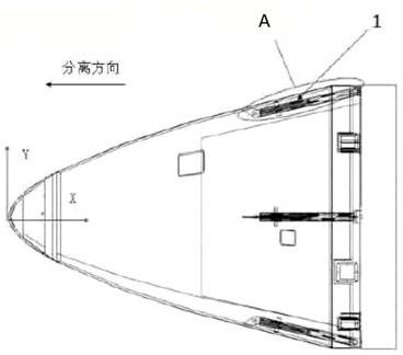
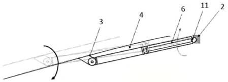
[0033] Such as Figure 1-Figure 5 As shown, a fairing obliquely pushes the axial separation device, including a spring separation mechanism, a flat ball socket base, and a hinge base;
[0034] The spring separation mechanism includes a sleeve, a separation spring and a spring push rod. The sleeve is a straight cylinder. In this embodiment, the sleeve is a straight cylinder, and one end thereof is set as a closed end. There is a first ear, the other end is open, the length of the separation spring is less than the length of the sleeve, the separation spring is arranged in the sleeve, and one end of it is embedded in the inner end surface of the closed end of the sleeve, so The spring push rod is a straight rod set in the sleeve, one end of which is provided with a flat ball head and the open end facing the sleeve is located outside the sleeve, and the other end is close to the other end of the separation spring, The separation spring pushes the spring push rod to provide thrus...
Embodiment 2
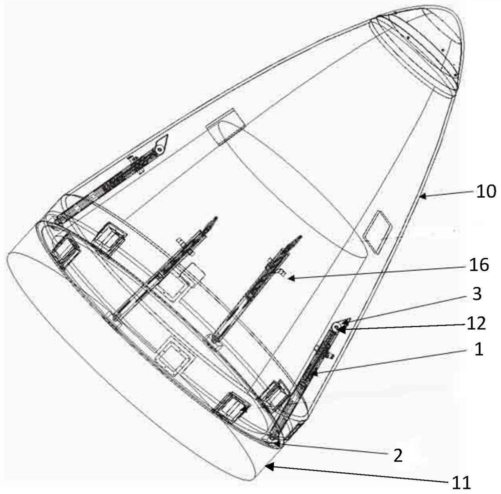
[0044] like Figure 1-Figure 6 As shown, a fairing obliquely pushes the axial separation device, including a spring separation mechanism, a flat ball socket base, and a hinge base;
[0045] The spring separation mechanism includes a sleeve, a separation spring and a spring push rod. The sleeve is a straight cylinder. In this embodiment, the sleeve is a straight cylinder, and one end thereof is set as a closed end. There is a first ear, the other end is open, the length of the separation spring is less than the length of the sleeve, the separation spring is arranged in the sleeve, and one end of it is embedded in the inner end surface of the closed end of the sleeve, so The spring push rod is a straight rod set in the sleeve, one end of which is provided with a flat ball head and the open end facing the sleeve is located outside the sleeve, and the other end is close to the other end of the separation spring, The separation spring pushes the spring push rod to provide thrust f...
PUM
| Property | Measurement | Unit |
|---|---|---|
| Angle | aaaaa | aaaaa |
Abstract
Description
Claims
Application Information