Hydraulic lifting structure for transfer trolley

A transfer vehicle and hydraulic technology, applied in the field of hydraulic support, can solve problems such as low handling efficiency and low cargo firmness

Inactive Publication Date: 2021-02-12
芜湖西格玛自动化装备有限公司
View PDF11 Cites 1 Cited by
  • Summary
  • Abstract
  • Description
  • Claims
  • Application Information

AI Technical Summary

Problems solved by technology

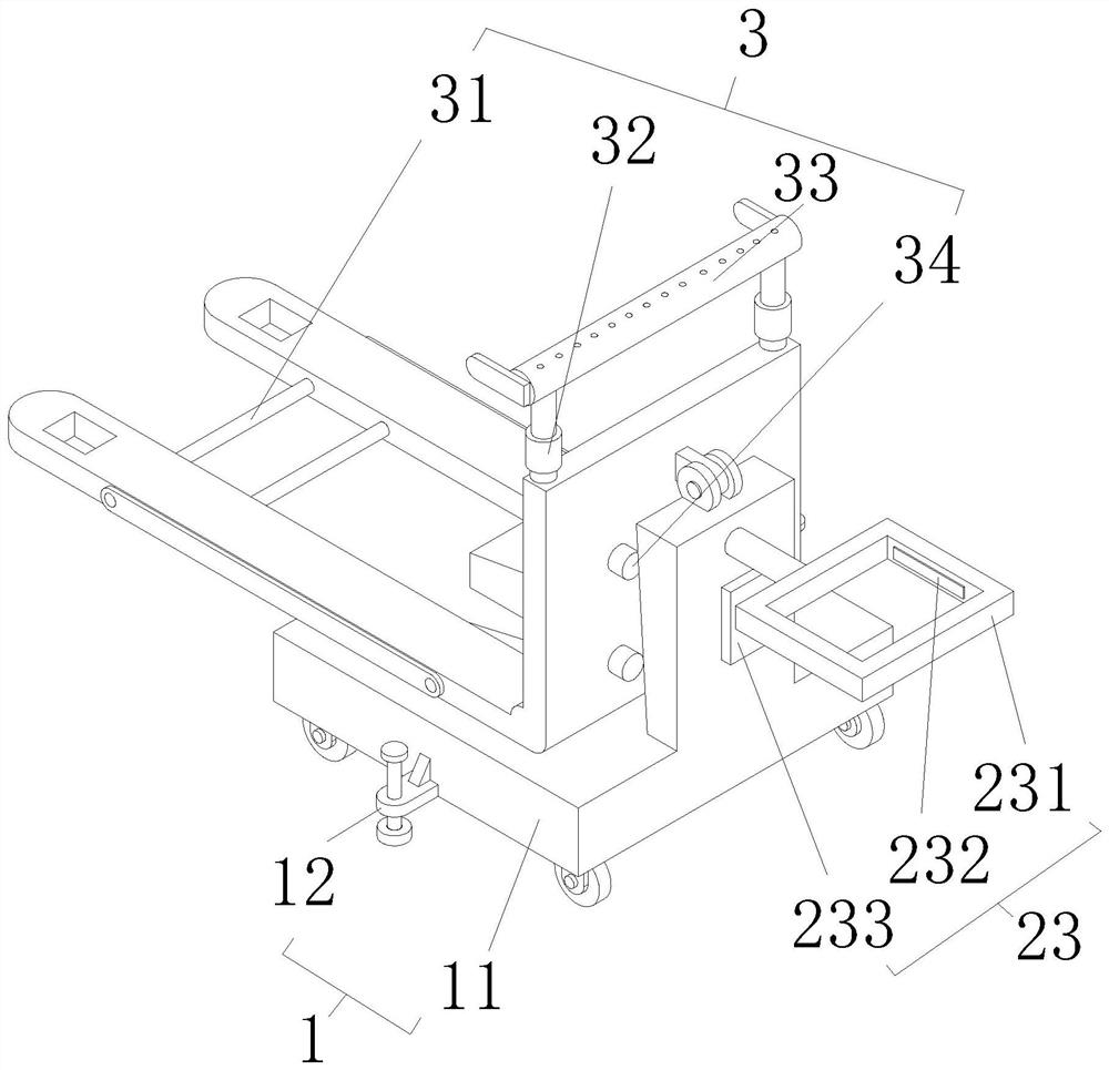
[0004] The forklift in the above patent can not only increase the length of the forklift through the reversible extension section, but also can be used to fix the goods to be transported, but the firmness of the goods fixed by the reversing structure is low, and after the cargo location needs to be manually adjusted for reversing, the handling efficiency is reduced. Therefore, it is necessary to design a hydraulic lifting structure of the transfer vehicle that is convenient for one-time stable loading of goods, convenient for the transfer of goods of different sizes, and can provide protection for the goods during the loading process.

Method used


Image

  • Hydraulic lifting structure for transfer trolley
  • Hydraulic lifting structure for transfer trolley
  • Hydraulic lifting structure for transfer trolley

Examples


Embodiment Construction

[0027]In order to facilitate the understanding of the present invention, the following will make a more comprehensive description of the present invention with reference to the relevant drawings. The drawings show several embodiments of the present invention, but the present invention can be implemented in different forms and is not limited to what is described in the text. On the contrary, these embodiments are provided to make the disclosure of the present invention more thorough and comprehensive.

[0028]It should be noted that when a component is called "fixed to" another component, it can be directly on the other component or there may be a centered component. When a component is considered to be "connected" to another component, it can be It is directly connected to another element or there may be a centered element at the same time. The terms "vertical", "horizontal", "left", "right" and similar expressions used herein are for illustrative purposes only.

[0029]Unless otherwise d...


PUM


Abstract

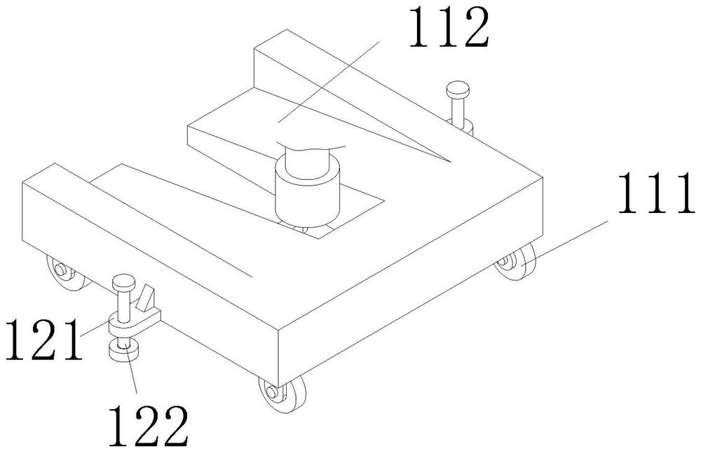
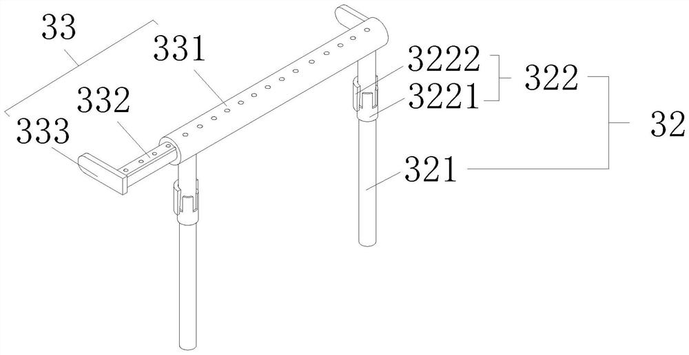
The invention discloses a hydraulic lifting structure for a transfer trolley. The hydraulic lifting structure comprises a base device, wherein the base device comprises a sliding seat, supporting assemblies are arranged on the side wall of the sliding seat, and a lifting device is arranged on the sliding seat; the lifting device comprises a forklift plate and a hydraulic cylinder, the side wall ofthe forklift plate is hinged to the sliding seat, the bottom of the hydraulic cylinder is hinged to the sliding seat, and the output end of the hydraulic cylinder is hinged to the bottom of the forklift plate; the hydraulic cylinder is connected with a control assembly through a wire, and the control assembly is arranged on one side of the sliding seat; the forklift plate is provided with a protection device, the protection device comprises an adjusting assembly, a lifting assembly and a buffering assembly, and the adjusting assembly is arranged on the side wall of the bottom of the forkliftplate; the lifting assembly comprises sliding rods, the sliding rods are slidably connected with the top of the forklift plate, the outer walls of the sliding rods are provided with a locking assemblyin a sleeved mode, and fixing assemblies are arranged on the sliding rods; and the buffering assembly is arranged on the side wall of the forklift plate. The invention aims to provide the hydraulic lifting structure for the transfer trolley convenient for one-time stable loading of goods, convenient for transferring of the goods with different sizes and capable of providing protection for the goods in the loading process.

Description

Technical field[0001]The present invention mainly relates to the technical field of hydraulic support, in particular to a hydraulic lifting structure of a transfer vehicle.Background technique[0002]People often use small forklifts when transporting larger goods. Small forklifts facilitate the lifting of goods and facilitate the transport of goods.[0003]According to a hydraulic forklift provided by the patent document with the application number CN201520226237.1, it is known that the product includes a hydraulic forklift body and an extension section. The hydraulic forklift body is provided with a clamping member for a fixed extension section and a movement that controls the extension section to flip Components, the reversible angle between the extension section and the hydraulic forklift body is 0-90°, the extension section is provided with reinforcing ribs, and the extension section has a wedge shape. The product can extend the length of the forklift through the reversible extensio...

Claims


Application Information

Patent Timeline
Patent Type & Authority Applications(China)
IPC IPC(8): B66F9/06B66F9/22B66F9/16B66F9/075F16F15/067B62B3/04
CPCB62B3/04B66F9/06B66F9/07504B66F9/0759B66F9/16B66F9/22F16F15/067
Inventor 彭雪雷井赛赛周学好黄明强
Owner 芜湖西格玛自动化装备有限公司
Why Eureka
Try Eureka