Buried electro-hydraulic switch machine

A switch machine, buried technology, applied in the direction of the locking mechanism for the switch, the hydraulic equipment for operating the switch or the circuit breaker, the electrical equipment for operating the switch or the circuit breaker, etc. Buried electro-hydraulic switch machines have complex structure, reduced equipment reliability, and low efficiency.

Active Publication Date: 2021-02-19
CRSC WANQUAN SIGNAL EQUIP
View PDF12 Cites 4 Cited by
  • Summary
  • Abstract
  • Description
  • Claims
  • Application Information

AI Technical Summary

Problems solved by technology

[0005] Aiming at the existing problems in the prior art that the structure of the buried electro-hydraulic switch machine is complicated, the reliability of the whole equipment is reduced, and the efficiency is low, the object of the present invention is to provide a buried type electro-hydraulic switch machine, including switch Machine casing, EHA electro-hydraulic actuator system, action lever mechanism, indicating lever mechanism, node base system and manual operating system, the EHA electro-hydraulic actuator system is fixed on the corresponding mounting seat of the switch machine casing, and the action The lever mechanism is plugged into the corresponding through hole of the switch machine casing, the action lever mechanism includes a starting mechanism, and the starting mechanism is clamped on the EHA electro-hydraulic actuator system, and the indicating lever mechanism is installed on the switch At the corresponding installation position of the switch machine case, the node base system is fixed on the installation base of the switch machine case, the node base system is located between the action lever mechanism and the indication lever mechanism, and the manual The operating system is connected with the actuating rod mechanism, the structure of this buried electro-hydraulic switch machine is simple, the operation efficiency of the whole equipment is higher, and it is more convenient to use in road traffic

Method used


Image

  • Buried electro-hydraulic switch machine
  • Buried electro-hydraulic switch machine
  • Buried electro-hydraulic switch machine

Examples


Embodiment Construction

[0029] The technical solutions of the present invention will be further described below in conjunction with specific embodiments. The following examples are only intended to provide a possible solution, and are not intended to limit the present invention.

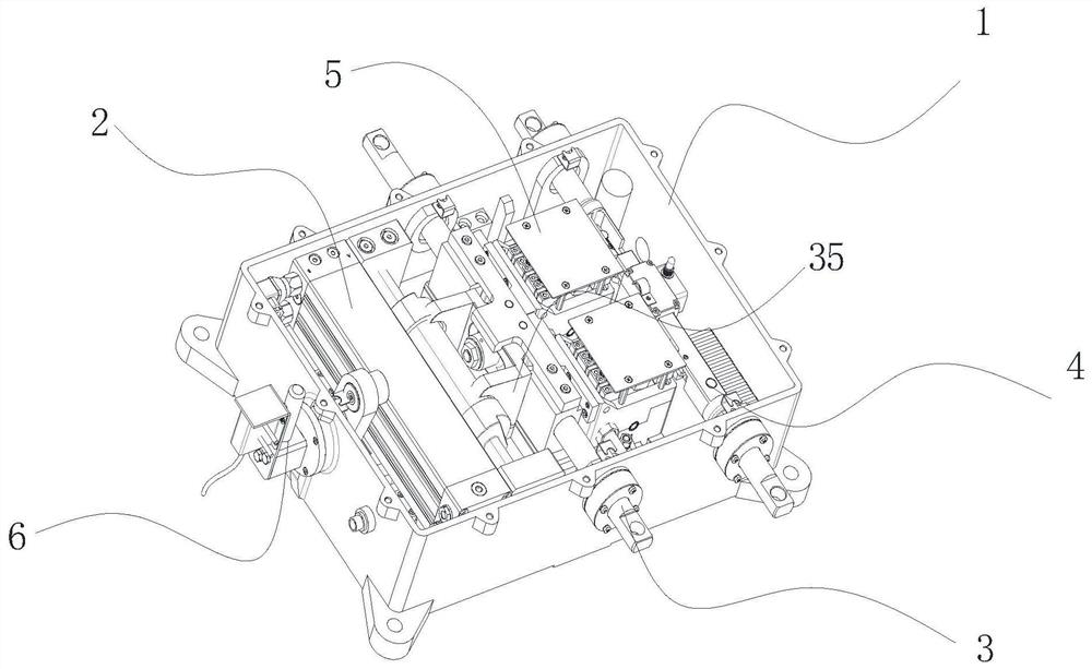
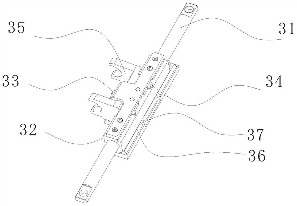
[0030] An underground electro-hydraulic switch machine, such as figure 1As shown, it includes switch machine casing 1, EHA electro-hydraulic actuator system 2, action lever mechanism 3, indication lever mechanism 4, node base system 5 and manual operating system 6, wherein EHA electro-hydraulic actuator system 2 is fixed on the switch The machine casing 1 corresponds to the mounting seat, and the action lever mechanism 3 is plugged into the corresponding through hole of the switch machine casing 1. Moreover, the action lever mechanism 3 includes a starting mechanism 35, and the starting mechanism 35 is clamped to the EHA electro-hydraulic actuator system 2. On the top, the indicating lever mechanism 4 is installed at the c...


PUM


Abstract

The invention discloses a buried electro-hydraulic point switch, and belongs to the technical field of railway traffic equipment. In order to solve the problems of complex structure, reduced reliability of the whole equipment and low efficiency of a buried electro-hydraulic switch machine in the prior art, the invention provides a buried electro-hydraulic switch machine. The buried electro-hydraulic switch machine comprises a switch machine shell, an EHA electro-hydraulic execution system, an actuating rod mechanism, an indication rod mechanism, a node seat system and a manual operation system, wherein the EHA electro-hydraulic execution system is fixed on a corresponding mounting seat of the switch machine shell, the actuating rod mechanism is inserted into a corresponding through hole ofthe switch machine shell, the actuating rod mechanism comprises a starting mechanism, the starting mechanism is clamped on the EHA electro-hydraulic execution system, the indication rod mechanism ismounted at a corresponding mounting position of the switch machine shell, the node seat system is fixed to the switch machine shell mounting seat, and the manual operation system is connected with theactuating rod mechanism. The buried electro-hydraulic switch machine is simple in structural design, easy to operate, higher in operation efficiency of the whole equipment and more convenient to usein road traffic.

Description

technical field [0001] The invention belongs to the technical field of railway traffic equipment, in particular to an underground electro-hydraulic switch machine. Background technique [0002] The national conditions of my country's large population determine the long-term implementation of the strategy of "prioritizing the development of public transportation". Urban rail transit has gradually become the focus of public transportation development in tourist cities and urban agglomerations. In recent years, due to the stable development of the economy and the strong support of the government, the construction of urban rail transit in my country has gradually expanded, and it has become the largest market for urban rail transit construction in the world. In the tram project, urban rail transit transportation line facilities are on urban roads, and it is inevitable to cross and share the road with pedestrians and other vehicles. Therefore, the starting point of the design of...

Claims


Application Information

Patent Timeline
Patent Type & Authority Applications(China)
IPC IPC(8): B61L5/04B61L5/06B61L5/10
CPCB61L5/045B61L5/06B61L5/10
Inventor 李金海蒉凯腾周苗吴思源宋微微王宏亮
Owner CRSC WANQUAN SIGNAL EQUIP
Why Eureka
Try Eureka