Reinforced hoisting machinery connecting shaft
A hoisting machine and connecting shaft technology, applied in the directions of cranes, traveling mechanisms, load suspending elements, etc., can solve the problems of connecting shaft lifting limitation, low safety, connecting shaft shaking, etc., so as to avoid device displacement and improve Applicability, safety-enhancing effect
- Summary
- Abstract
- Description
- Claims
- Application Information
AI Technical Summary
Problems solved by technology
Method used
Image
Examples
Embodiment 1
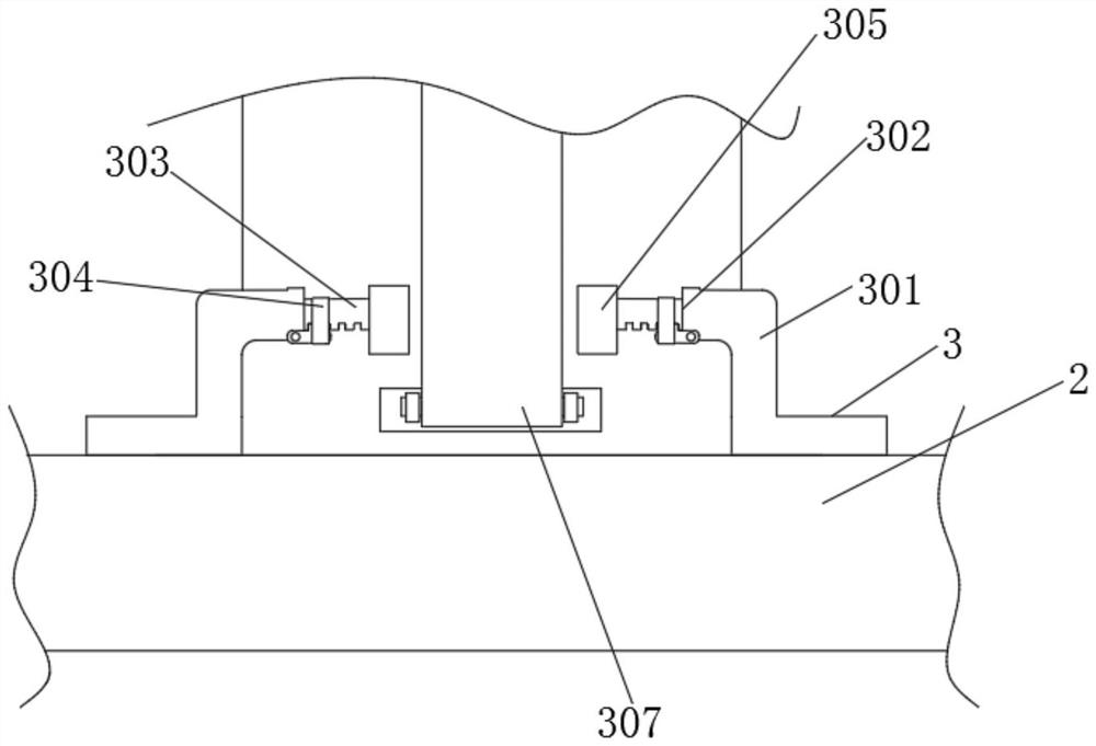
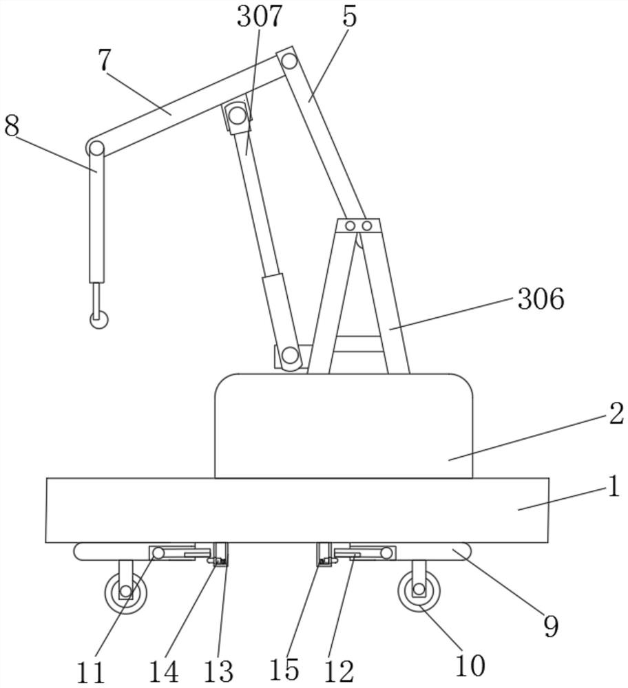
[0023] Example 1, such as figure 1 As shown, the present invention provides a reinforced hoisting machinery connection shaft, including a bottom plate 1 , a workbench 2 is fixedly connected to the top of the bottom plate 1 , and a fixing mechanism 3 is arranged on the top of the workbench 2 .
[0024] Let's talk about the specific setting and function of the fixing mechanism 3 in detail.
[0025] Fixing mechanism 3 comprises fixing bracket 301, and fixing bracket 301 is provided with two, and the bottom of another fixing bracket 301 is fixedly connected with the top of workbench 2, and the opposite side of two fixing brackets 301 is all provided with through groove 302, two The inner surfaces of each through groove 302 are movably connected with a rack 303, the outer surface of the fixed bracket 301 is located below the through groove 302 and is connected with a fixed casing 304 through a rotating shaft, and the inside of the fixed casing 304 is fixedly connected with a clampi...
Embodiment 2
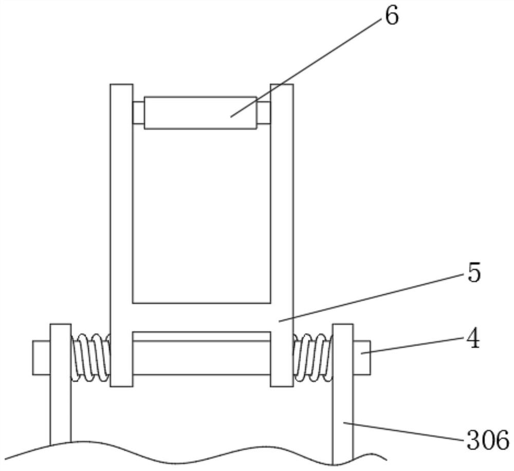
[0027] Example 2, such as figure 2 with 3 As shown, a crossbar 4 is fixedly connected between the two sides of the top of the base 306, the outer surface of the crossbar 4 is rotatably connected with a hanger 5, and the two sides of the top of the hanger 5 are rotatably connected with a rotating sleeve 6, and the rotating sleeve The outer surface of shell 6 is fixedly connected with connecting rod 7, the two sides of the bottom of connecting rod 7 are connected with the both sides of automatic telescopic rod 307 top, and the other end of connecting rod 7 is connected with lifting rod 8 in rotation. An automatic telescopic rod 307 is connected between the base 306, the hanger 5 and the connecting rod 7. When the hanger 5 hoists the connecting rod 7, it is easy to avoid shaking after the connecting rod 7 is lifted by the force of a single direction. As well as the problem of instability, the automatic telescopic rod 307 can serve as an auxiliary support for the connecting rod ...
Embodiment 3
[0028] Example 3, such as figure 2 As shown, both sides of the bottom of the base plate 1 are fixedly connected with a fixed strip 9, the bottom of the fixed strip 9 is fixedly connected with a roller 10, the bottom of the fixed strip 9 is provided with a dark groove 11, and the inner surface of the dark groove 11 is rotatably connected with a limit rod 12. The bottom of the bottom plate 1 is fixedly connected with a fixed frame 13, and the outer surface of the fixed frame 13 is penetrated with a fixed column 14. It is movably connected with the outer surface of the roller 10. A device that can limit the rolling of the roller 10 is added at the bottom of the crane. When the crane is working, the fixed column 14 is pushed to the inside of the fixed frame 13, and the stop bar 12 is put down to contact the outer surface of the roller 10. The limit function is performed to prevent the device from sliding down when it encounters an uneven bottom surface, thereby improving the saf...
PUM
 Abstract
Description
Claims
Application Information
 - R&D Engineer
- R&D Manager
- IP Professional
- Industry Leading Data Capabilities
- Powerful AI technology
- Patent DNA Extraction
Browse by: Latest US Patents, China's latest patents, Technical Efficacy Thesaurus, Application Domain, Technology Topic, Popular Technical Reports.
© 2024 PatSnap. All rights reserved.Legal|Privacy policy|Modern Slavery Act Transparency Statement|Sitemap|About US| Contact US: help@patsnap.com


