
Oil bottling and tightening equipment

A bottling and oil technology, applied in bottling machines, packaging, synchronization devices, etc., can solve problems such as large equipment costs, oil pouring, and large bottle caps

Inactive Publication Date: 2021-02-19
DONGGUAN UNIV OF TECH
View PDF0 Cites 0 Cited by
  • Summary
  • Abstract
  • Description
  • Claims
  • Application Information

AI Technical Summary

Problems solved by technology

[0002] Oils, especially edible oils, such as camellia oil and rapeseed oil, need to be bottled. According to different needs, the volume of bottling is also different. The large ones are dozens of liters, while the small ones are about 1L. It is very convenient to bottle and tighten large-volume oil bottles. Due to the large size of the oil bottle, even the empty oil bottle can be directly transported through the conveyor belt. It is positioned with the photoelectric door technology, and the bottle cap is also relatively large. The weight of the liquid is large, and it will not drive the oil bottle to rotate during the process of tightening the cap. However, for a small-volume oil bottle, its mass is small. , still shakes, which will cause the oil to pour out, so most of the existing technologies use manual screw caps, or set up special clamping equipment to clamp them during the tightening operation, so the delivery device needs to be Specific structural design and coordination will consume a large equipment cost

Method used


Image

  • Oil bottling and tightening equipment
  • Oil bottling and tightening equipment
  • Oil bottling and tightening equipment

Examples


Embodiment Construction

[0019] In order to enable those skilled in the art to better understand the technical solution of the present invention, the present invention will be described in detail below in conjunction with the accompanying drawings. The description in this part is only exemplary and explanatory, and should not have any limiting effect on the protection scope of the present invention. .

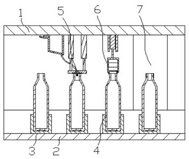
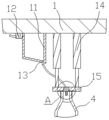
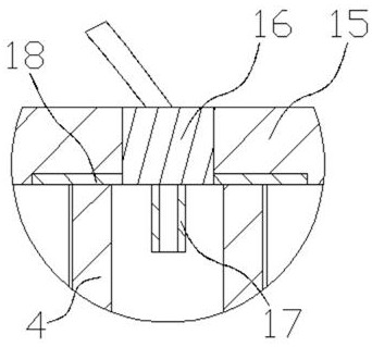
[0020] Such as figure 1 , Figure 6 and Figure 7 As shown, the specific structure of the present invention is: a kind of oil bottle screwing equipment, comprising a frame 1 and a conveying device 2 arranged at the bottom of the frame 1, the conveying device 2 is provided with a The carrier 3, the frame 1 is also provided with an oil filling device 5 cooperating with the oil bottle 4, a capping device 6 and a tightening device 7 along the conveying direction, and the described tightening device 7 includes a tightening lifting structure and is arranged on Tighten the tightener 35 below the lifting st...


PUM


Abstract

The invention relates to oil bottling and tightening equipment which comprises a rack and a conveying device. Carriers cooperating with oil bottles are arranged on the conveying device, and an oil injection device cooperating with the oil bottles, a capping device and a tightening device are further arranged on the rack in the conveying direction. The tightening device comprises a tightening lifting structure and a tightener. The tightener comprises a tightening motor, a tightening rotating shaft sleeve and a tightening limiting seat, all of which are arranged on the tightening lifting structure, a rotating shaft of the tightening motor is connected with a tightening rotating sleeve in the vertical direction, the tightening rotating sleeve cooperates with bottle caps, at least three tightening clamping rods which are annularly distributed are arranged below the tightening limiting seat, all the tightening clamping rods incline outwards and downwards, tightening clamping wheels are arranged at the lower ends of the tightening clamping rods, and the annular center line of the tightening clamping rods distributed annularly coincides with the center line of the tightening rotating sleeve. Shaking, toppling and the like of the oil bottles in the tightening process can be avoided, meanwhile, specific structural design does not need to be carried out on the conveying device, and the equipment cost is saved while automatic tightening is achieved.

Description

technical field [0001] The invention relates to the field of packaging equipment, in particular to an oil bottle tightening equipment. Background technique [0002] Oils, especially edible oils, such as camellia oil and rapeseed oil, need to be bottled. According to different needs, the volume of bottling is also different. The large ones are dozens of liters, while the small ones are about 1L. It is very convenient to bottle and tighten large-volume oil bottles. Due to the large size of the oil bottle, even the empty oil bottle can be directly transported through the conveyor belt. It is positioned with the photoelectric door technology, and the bottle cap is also relatively large. The weight of the liquid is large, and it will not drive the oil bottle to rotate during the process of tightening the cap. However, for a small-volume oil bottle, its mass is small. , still shakes, which will cause the oil to pour out, so most of the existing technologies use manual screw caps,...

Claims


Application Information

Patent Timeline
IPC IPC(8): B67C7/00B67B3/20B67C3/16
CPCB67C7/0026B67B3/206B67B3/2066B67C3/16B67C2007/006B67C2007/0066
Inventor 何楚亮
Owner DONGGUAN UNIV OF TECH
Learn More