Computer vision structure vibration monitoring method based on motion compensation

A computer vision and motion compensation technology, applied in the testing, calculation, and elasticity testing of machine/structural components, can solve problems such as changes in monitoring results, affecting measurement accuracy, and angle changes, reducing labor costs and improving monitoring accuracy. High, simple equipment effect

Active Publication Date: 2021-02-19
ZHEJIANG UNIV
View PDF6 Cites 4 Cited by
  • Summary
  • Abstract
  • Description
  • Claims
  • Application Information

AI Technical Summary

Problems solved by technology

However, it is impractical to completely fix the camera for a long time. Factors such as driving near vehicles and loose fixing devices will change the position or angle of the camera, resulting in changes in monitoring results.
Therefore, the computer vision monitoring method based on the assumption that the camera is completely fixed has errors in the monitoring itself, which affects the measurement accuracy

Method used


Image

  • Computer vision structure vibration monitoring method based on motion compensation
  • Computer vision structure vibration monitoring method based on motion compensation

Examples


Embodiment Construction

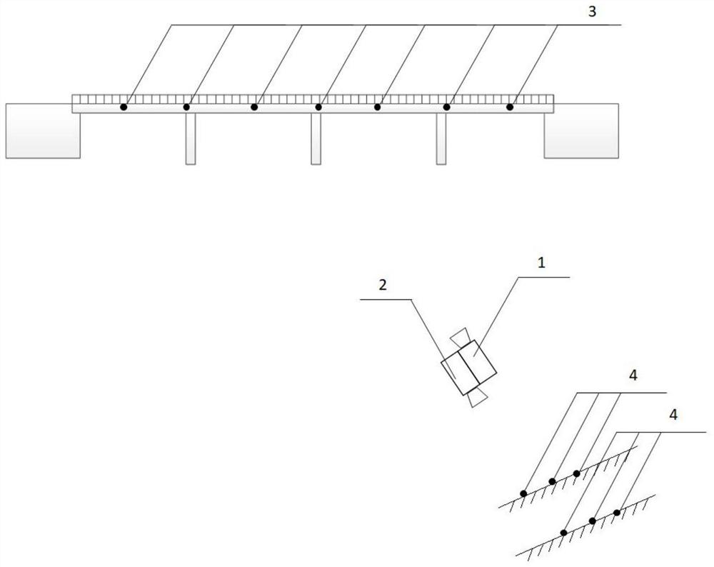
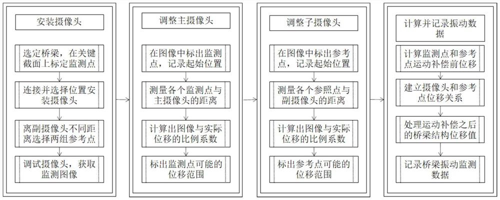
[0047] The following combination figure 1 The schematic diagram of the instrument arrangement shown in and figure 2 The implementation flow chart shown in further illustrates the specific embodiment of the present invention. The specific steps are as follows:

[0048] A computer vision structural vibration monitoring method based on motion compensation, comprising the following steps:

[0049] A install the camera;

[0050] A1. Select a number of monitoring positions in key areas such as the fulcrum of the bridge to be tested, the mid-span, and the anchor point of the cable, and select the position with obvious contour features as the monitoring point 3;

[0051] A2. Rigidly connect the main camera 1 and the sub-camera 2, select the installation location, align the main camera with the monitoring bridge, and the sub-camera with the nearby wall or ground where no displacement is assumed;

[0052]A3. On the wall or the ground within the monitoring range of the secondary cam...


PUM


Abstract

The invention provides a computer vision structure vibration monitoring method based on motion compensation. Self-motion compensation is carried out by utilizing a double-camera system. The double-camera system is composed of a main camera and an auxiliary camera which are in rigid connection with each other. The main camera directly measures the structural displacement,. The method inevitably haserrors caused by the movement of the main camera. Meanwhile, the auxiliary camera measures the displacement of the double-camera system in translation and rotation, and is used for estimating the measurement error caused by the movement of the main camera. Then, the measurement error is subtracted from the displacement directly measured by the main camera to obtain the corrected structural displacement so that the vibration monitoring of the bridge structure is truly and accurately realized.

Description

technical field [0001] The invention relates to a computer vision structure vibration monitoring method. Background technique [0002] Due to imperfect design theory, material limitations during construction, poor construction quality and other initial defects in some bridge structures, there are relatively large safety hazards. After the bridge is completed and in operation, it is subject to the cumulative effects of various loads, including self-weight, prestress, traffic, temperature changes and stress redistribution caused by damage, etc., and will experience long-term structural deformation and performance degradation. In addition, bridges in service may experience structural damage due to the impact of earthquakes, typhoons and other disastrous factors. Problems such as initial defects, performance degradation, and structural damage of bridges cause bridge collapse accidents to continue to emerge, causing a large number of economic losses and casualties. Therefore, br...

Claims


Application Information

Patent Timeline
Patent Type & Authority Applications(China)
IPC IPC(8): G01H9/00G01B11/02
CPCG01H9/00G01B11/02G06T7/0004G06T7/292G01M5/0008G01M5/0066G01M5/0091G01M5/0058G06T7/70G06T2207/30232
Inventor 叶肖伟李哲勋金涛
Owner ZHEJIANG UNIV
Why Eureka
Try Eureka