Intelligent anchorage device and method for testing axial force of anchor rod by using intelligent anchorage device

An anchorage, intelligent technology, applied in the direction of measuring force, installing anchor rods, measuring devices, etc., can solve problems such as increasing the amount of earthwork excavation, hidden dangers in engineering safety, expensive dynamometers, etc., to achieve good response and ensure The effect of project safety and project cost saving

Pending Publication Date: 2021-02-19
HUAQIAO UNIVERSITY
View PDF0 Cites 5 Cited by
  • Summary
  • Abstract
  • Description
  • Claims
  • Application Information

AI Technical Summary

Problems solved by technology

At present, the monitoring of the axial force of the anchor is mainly by installing a dynamometer under the anchorage of the anchor head to monitor the axial force of the anchor. This existing method has two main disadvantages: (1) the dynamometer is very expensive, Generally, the market price of a dynamometer is 900-3000 yuan, or even more expensive; and the dynamometer is a one-time consumption product, and the number of anchor rods in an anchoring project ranges from more than a hundred to more than a thousand. It is difficult to monitor the axial force of a large number of bolts in batches, which leads to the fact that in actual projects, a few bolts in a column of 1-3 sections are mostly selected for monitoring, and what is the change of the axial force of most unmonitored bolts? Does the actual axial force exceed the design value? Is the actual axial force much lower than the design value? Is the axial force fluctuation abnormal? (2) The size of the dynamometer is large, especially the axial length is long, and it needs to occupy a certain clearance, resulting in the clear distance between the support pile or the support slope and the basement exterior wall. Increased, increasing the amount of earthwork excavation and prolonging the construction period

Method used


Image

  • Intelligent anchorage device and method for testing axial force of anchor rod by using intelligent anchorage device
  • Intelligent anchorage device and method for testing axial force of anchor rod by using intelligent anchorage device
  • Intelligent anchorage device and method for testing axial force of anchor rod by using intelligent anchorage device

Examples


Embodiment Construction

[0090] In order to further explain the technical solution of the present invention, the following will be described in detail in conjunction with the examples.

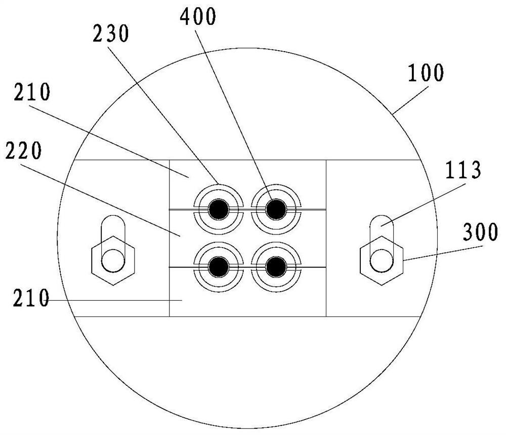
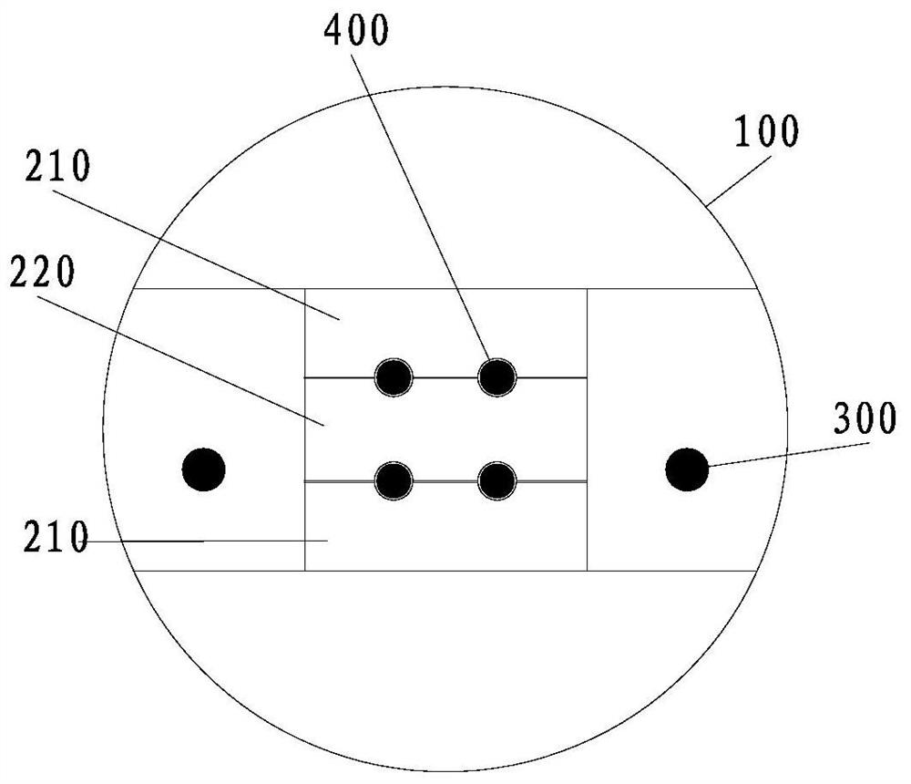
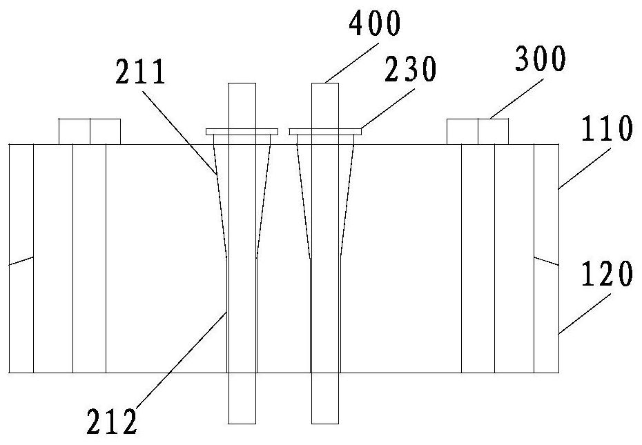
[0091] refer to Figure 1 to Figure 39 , the present invention firstly proposes a self-unlocking anchor for recoverable anchor rods, specifically referring to Figure 1 to Figure 22 , comprising an anchor ring 100, a split anchor 200 for clamping an anchor steel strand, a clip 230 and a T-shaped screw 300. In an embodiment, the anchor steel strand is a steel strand 400, and the anchor ring 100 Set outside the split anchor 200. The anchor ring 100 includes a first anchor ring 110 and a second anchor ring 120, the first anchor ring 110 includes an upper end ring 114 and two upper wedge platforms 111 separately arranged on the upper side of the upper end ring 114, the two Each upper wedge platform 111 is provided with a continuous elongated unlocking groove 113 , the unlocking groove 113 penetrates from the upper end s...


PUM


Abstract

The invention relates to an intelligent anchorage device, which comprises anchor rings and a split type anchorage device body used for clamping an anchor rod steel strand, wherein the anchor rings comprise a first anchor ring and a second anchor ring, the first anchor ring and the second anchor ring are locked together through a connecting piece, an anchorage device mounting groove used for mounting the split type anchorage device body is defined by the first anchor ring and the second anchor ring, the intelligent anchorage device further comprises a strain gauges used for sensing the circumferential strains of the anchor rings, compensation gauges used for compensating strain difference caused by temperature, and a data collector, and the strain gauges are connected to the data collectorthrough conducting wires, and are fixed to the outer walls of the anchor rings in the circumferential directions of the anchor rings. The invention further provides a method for testing the axial force of an anchor rod by adopting the intelligent anchorage device. The intelligent anchorage device has the advantages of being simple in structure, convenient to operate and high in measurement precision.

Description

technical field [0001] The invention relates to an intelligent anchor and its method for testing the axial force of the anchor, which is applicable to the monitoring of the axial force of the anchor in all temporary anchoring projects. Obtain the axial force borne by the bolt. The invention can replace the traditional method of testing the axial force of the anchor rod by setting a dynamometer under the anchorage. Background technique [0002] In engineering construction, there are more and more geotechnical anchoring projects, and the reusability of related materials is of great significance for saving resources. In geotechnical anchoring engineering, due to the complexity of construction conditions, site environment, geological conditions, etc., the safety of the anchor rod is directly related to the safety and stability of the anchoring engineering. The most important indicator of bolt safety monitoring is the monitoring of bolt axial force. At present, the monitoring ...

Claims


Application Information

Patent Timeline
Patent Type & Authority Applications(China)
IPC IPC(8): G01L1/22E02D5/74E21D21/00E21D21/02
CPCE02D5/74E21D21/0026E21D21/02E21D21/006G01L1/22
Inventor 涂兵雄林振德贾金青侯军军李志伟肖朝昀程强黄金狮程继宝章钧翔
Owner HUAQIAO UNIVERSITY
Why Eureka
Try Eureka