Chip bonding pad slicing method

A welding pad and chip technology, applied in the field of semiconductor failure analysis, can solve problems such as chip pad cracking, achieve the effect of preventing cracking, reducing impact, and ensuring normal analysis

Active Publication Date: 2021-02-19
QINGDAO GOERTEK MICROELECTRONICS RES INST CO LTD
View PDF9 Cites 1 Cited by
  • Summary
  • Abstract
  • Description
  • Claims
  • Application Information

AI Technical Summary

Problems solved by technology

[0003] The main purpose of the present invention is to propose a method for slicing chip pads, which aims to solve the technical problem that the existing chip pad slicing method easily causes chip pads to break

Method used


Image

  • Chip bonding pad slicing method
  • Chip bonding pad slicing method
  • Chip bonding pad slicing method

Examples


Embodiment Construction

[0048] The technical solutions in the embodiments of the present invention will be clearly and completely described below in conjunction with the accompanying drawings in the embodiments of the present invention. Obviously, the described embodiments are only part of the embodiments of the present invention, not all of them. Based on the embodiments of the present invention, all other embodiments obtained by persons of ordinary skill in the art without creative work all belong to the protection scope of the present invention.

[0049] It should be noted that if there are directional indications (such as up, down, left, right, front, back...) in the embodiment of the present invention, the directional indications are only used to explain the position in a certain posture (as shown in the accompanying drawings). If the specific posture changes, the directional indication will also change accordingly.

[0050] In addition, if there are descriptions involving "first", "second" and ...


PUM


Abstract

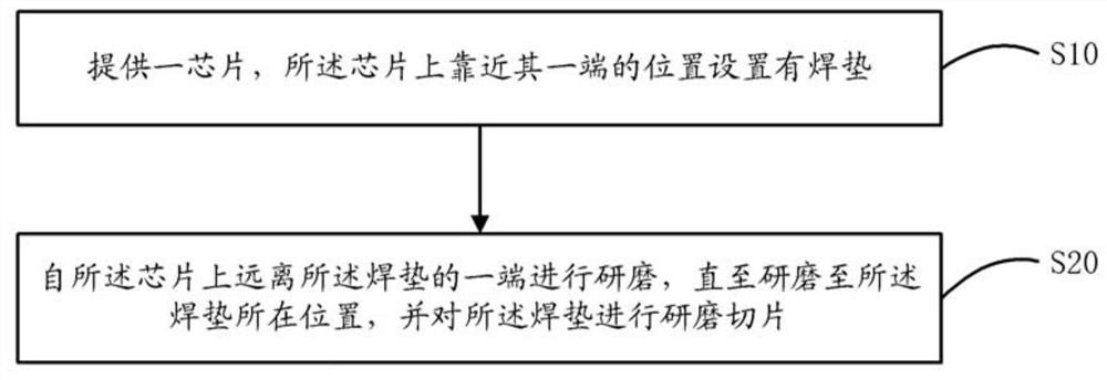
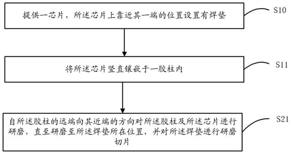
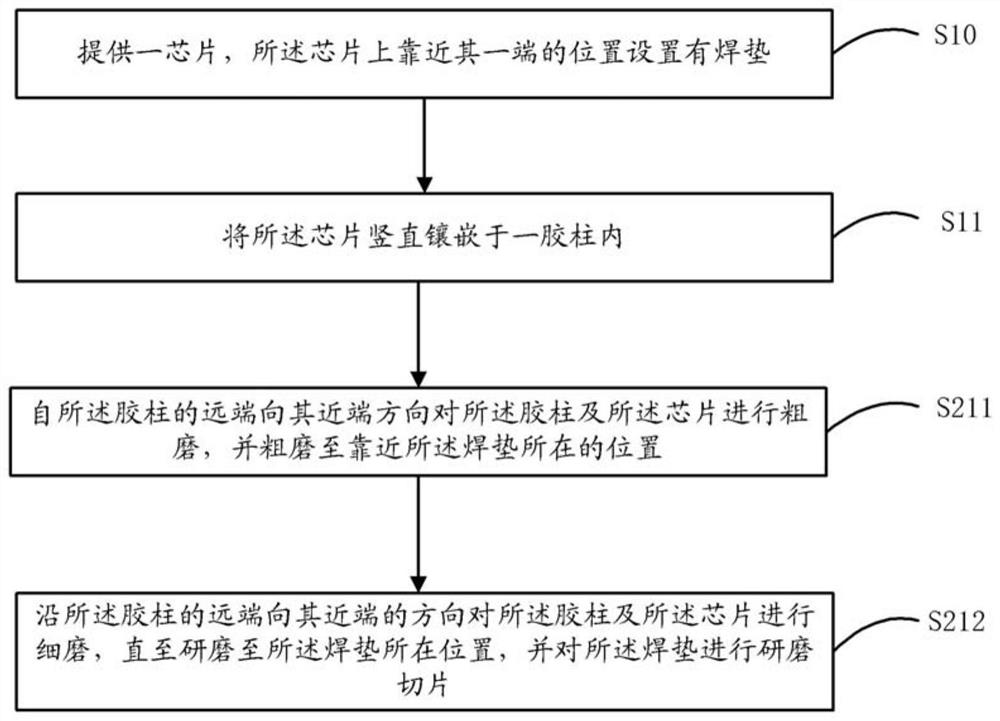
The invention discloses a chip bonding pad slicing method, which comprises the following steps of: providing a chip, and arranging a bonding pad at a position on the chip, which is close to one end ofthe chip; and grinding one end, far away from the welding pad, of the chip until the end is ground to the position of the welding pad, and grinding and slicing the welding pad. According to the slicing method of the chip bonding pad, the initial slicing position is set at the end, away from the bonding pad, of the chip, so that grinding can be conducted from the end, away from the bonding pad, ofthe chip until the bonding pad is ground to the position where the bonding pad is located, and grinding and slicing are conducted on the bonding pad; and compared with an existing method for grindingand slicing from the position near the bonding pad, the slicing method of the invention changes the slicing direction, grinding is conducted from the end, away from the bonding pad, of the chip to the end where the bonding pad is located, the influence on the chip bonding pad in the slicing process can be reduced, the chip bonding pad is prevented from being broken, and then subsequent normal analysis is guaranteed.

Description

technical field [0001] The invention relates to the technical field of semiconductor failure analysis, in particular to a method for slicing chip pads. Background technique [0002] For surface and internal defect inspection of electronic components, SMT process failure analysis, PCB and component abnormality analysis, it is usually necessary to slice the chip pad. At present, the slicing method for chip pads of Low-K materials is generally to start grinding and slicing from the position near the pads, that is, the direction closer to the target position. However, this method is easy to cause the pads to be affected by stress, resulting in Chip bonding pads are broken, seriously affecting subsequent analysis. Contents of the invention [0003] The main purpose of the present invention is to propose a method for slicing chip pads, aiming to solve the technical problem that the existing slicing method for chip pads easily causes the chip pads to break. [0004] In order to...

Claims


Application Information

Patent Timeline
Patent Type & Authority Applications(China)
IPC IPC(8): G01N1/06G01N1/28G01N1/32
CPCG01N1/06G01N1/286G01N1/32G01N2001/2866G01N2001/2873
Inventor 李彬彬
Owner QINGDAO GOERTEK MICROELECTRONICS RES INST CO LTD
Why Eureka
Try Eureka