A display screen reconstruction device and method
A technology for displaying images and image reconstruction, applied in neural learning methods, neural architectures, instruments, etc.
- Summary
- Abstract
- Description
- Claims
- Application Information
AI Technical Summary
Problems solved by technology
Method used
Image
Examples
Embodiment 1
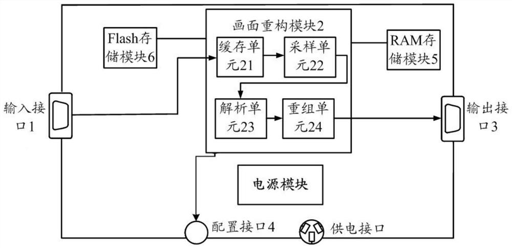
[0046] Such as figure 1 As shown, this embodiment provides a display screen reconstruction device, including: an input interface 1, connected to at least one receiving card, for receiving the picture driving signal sent by the receiving card, wherein the receiving card outputs the The picture information is converted into the corresponding picture driving signal; the picture reconstruction module 2 is connected with the input interface 1, used to connect with the input interface 1, used to receive the picture driving signal sent by the input interface 1, and sample and analyze the picture driving signal , parsed into a partial display image, and reorganize the partial display image to form a complete acquisition image; the output interface 3 is connected to the image reconstruction module 2, and is used to receive and output the complete acquisition image sent by the image reconstruction module 2.
[0047] In the above solution, the device for reconstructing the display screen...
Embodiment 2
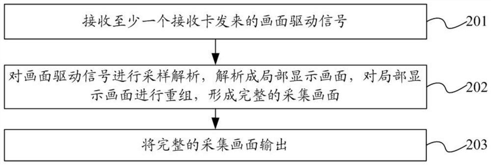
[0086] This embodiment proposes a display screen reconstruction method, such as figure 2 Shown include:
[0087] Step 201, receiving a picture driving signal from at least one receiving card, wherein the receiving card converts picture information output by a terminal device into a corresponding picture driving signal.
[0088] Step 202 , sampling and analyzing the image driving signal, analyzing it into a partial display image, and reorganizing the partial display image to form a complete acquisition image.
[0089] Step 203, outputting the complete captured picture.
[0090] In a specific embodiment, step 202 specifically includes:
[0091] Step 2021 , preprocessing the picture driving signal, completing the sampling and recording of the picture driving signal to obtain sampled and recorded data, wherein the picture driving signal output by each receiving card corresponds to a partial picture of the display screen.
[0092] Step 2022, performing data conversion on the sa...
Embodiment 3
[0103] Based on the display screen reconstruction device of this embodiment, the LED screen drive interface (protocol is one of the drive interface protocols such as 08 / 12 / 75) that the LED screen control circuit (i.e. the display screen reconstruction device) will apply, samples and The display screen is reconstructed and has universal applicability.
[0104] Regardless of whether it is a single receiving card or multiple receiving cards, you only need to reconstruct the display screen of each receiving card, perform collage or other image processing, and then you can reconstruct a complete display screen.
[0105] Such as figure 1 As shown, the hardware interface of the display screen reconstruction device mainly includes:
[0106] (1) LED screen drive signal input interface (that is, input interface 1): used to connect to the screen drive signal of the LED screen, and connected to the 08 / 12 / 75 drive interface of the original equipment.
[0107] (2) Display image driver out...
PUM
 Abstract
Description
Claims
Application Information
 - R&D
- Intellectual Property
- Life Sciences
- Materials
- Tech Scout
- Unparalleled Data Quality
- Higher Quality Content
- 60% Fewer Hallucinations
Browse by: Latest US Patents, China's latest patents, Technical Efficacy Thesaurus, Application Domain, Technology Topic, Popular Technical Reports.
© 2025 PatSnap. All rights reserved.Legal|Privacy policy|Modern Slavery Act Transparency Statement|Sitemap|About US| Contact US: help@patsnap.com


