
Marine submarine cable laying device and laying method thereof

A submarine cable and laying device technology, which is applied in the direction of cable laying equipment, cable installation, ground cable installation, etc., can solve the problems of reducing the service life of cables, affecting the effect of cable use, and damage to the cable protective layer, so as to prolong the service life , Guarantee the service life and prevent the effect of breaking

Inactive Publication Date: 2021-02-19
杨定娟
View PDF0 Cites 7 Cited by
  • Summary
  • Abstract
  • Description
  • Claims
  • Application Information

AI Technical Summary

Problems solved by technology

[0005] The present invention can solve the problem that when the existing equipment is laying the submarine cable, the pulling effect of the cable is poor, and the phenomenon of slipping is easy to occur when pulling the cable, resulting in damage to the protective layer on the outer side of the cable, reducing the service life of the cable, and the existing equipment When laying submarine cables, usually the cables can only be laid on the ground of the seabed, and the cables cannot be protected, causing the cables to be easily broken by external environmental factors and affecting the use of the cables.

Method used


Image

  • Marine submarine cable laying device and laying method thereof
  • Marine submarine cable laying device and laying method thereof
  • Marine submarine cable laying device and laying method thereof

Examples


Embodiment Construction

[0033] The embodiments of the present invention will be described in detail below with reference to the accompanying drawings, but the present invention can be implemented in many different ways defined and covered by the claims.

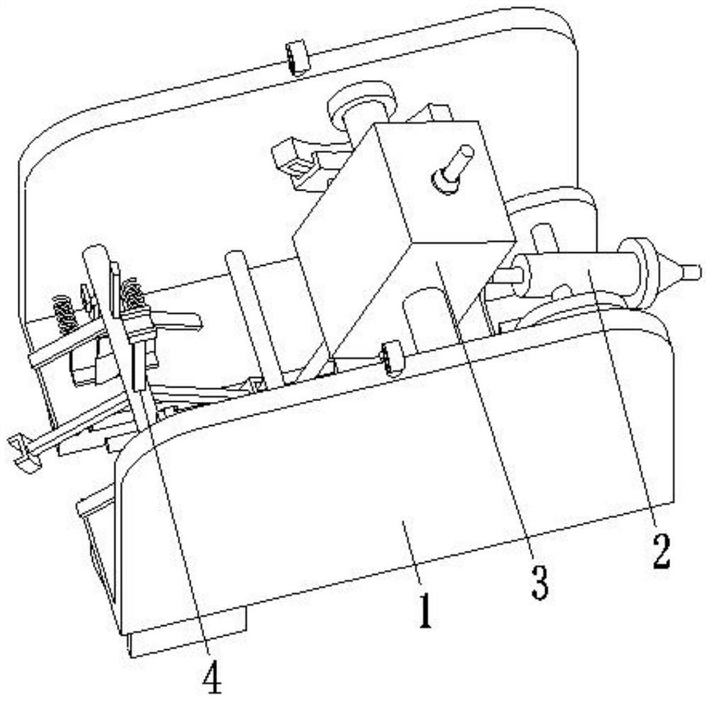
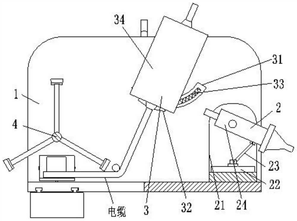
[0034] Such as Figure 1 to Figure 6 As shown, a marine submarine cable laying device includes a fixing frame 1, a slotting device 2, a wire pulling device 3 and a landfill device 4. The fixing frame 1 is in a U-shaped structure, and the lower end of the left side of the fixing frame 1 is provided with a rectangular Groove, the slotting device 2 is installed on the right side inside the fixed frame 1, the backguy device 3 is installed on the middle part inside the fixed frame 1, and the landfill device 4 is installed on the left side inside the fixed frame 1.

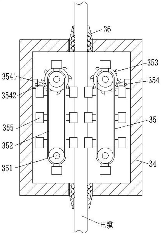
[0035] The slotting device 2 includes a mounting frame 21, an electric slider 22, a support rod 23 and a high-pressure nozzle 24. The mounting frame 21 is in a U-shaped structure, and the int...


PUM


Abstract

The present invention relates to a marine submarine cable laying device and a laying method thereof. The marine submarine cable laying device comprises a fixing frame, a slotting device, a cable pulling device and a landfill device, the fixing frame is of a U-shaped structure, and the slotting device is installed at the right side of the interior of the fixing frame. The cable pulling device is installed in the middle of the interior of the fixing frame, and the landfill device is installed at the left side of the interior of the fixing frame. The marine submarine cable laying device and the laying method thereof can solve the problems that when an existing device is used for laying submarine cables, the cable pulling effect is poor, slipping is likely to happen in the cable pulling process, a protection layer at the outer side of the cables is damaged, the service life of the cables is shortened; and when the existing device is used for laying the submarine cables, only the cables canbe laid on the submarine ground generally, and the cable cannot be protected, so that the cable is easily broken by external environmental factors, and the use effect of the cable is influenced.

Description

technical field [0001] The invention relates to the field of marine submarine cable laying, in particular to a marine submarine cable laying device and a laying method thereof. Background technique [0002] Submarine cables are cables wrapped in insulating material and laid on the seabed for telecommunications transmission. Submarine cables are divided into submarine communication cables and submarine power cables. Modern undersea cables use fiber optics to transmit telephone and internet signals. The world's first submarine cable was laid between England and France in 1850. China's first submarine cable was completed in 1988. [0003] At present, when the existing submarine cables are laid, the following defects usually exist: 1. When the existing equipment is laying the submarine cables, the pulling effect of the cables is poor, and the phenomenon of slipping is prone to occur when pulling the cables, resulting in the protection of the outer side of the cables. 2. When...

Claims


Application Information

Patent Timeline
IPC IPC(8): H02G1/10H02G9/02
CPCH02G1/10H02G9/02
Inventor 杨定娟
Owner 杨定娟
Learn More