Screw device

A technology of screw and screw shaft, which is applied in the direction of measuring device, transmission device, electric device, etc., and can solve problems such as peeling

Active Publication Date: 2021-02-19
THK CO LTD
View PDF26 Cites 2 Cited by
  • Summary
  • Abstract
  • Description
  • Claims
  • Application Information

AI Technical Summary

Problems solved by technology

When the screw device is used for a long time in an environment where a large axial load is applied, damage such as peeling may occur on the surface of the screw groove of the screw shaft

Method used


Image

  • Screw device
  • Screw device
  • Screw device

Examples


no. 1 approach

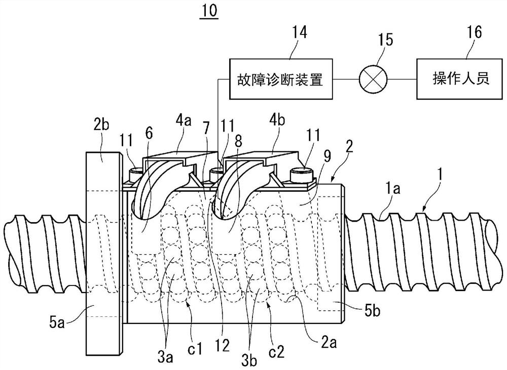
[0022] figure 1 A side view showing the screw device 10 according to the first embodiment of the present invention. 1 is a screw shaft, 2 is a nut, 3a, 3b are balls which are rolling elements interposed between them, 4a, 4b are return pipes which are circulation parts.

[0023] A helical screw groove 1 a is formed on the outer surface of the screw shaft 1 . The cross-sectional shape of the threaded groove 1a is a pointed arch. The balls 3a, 3b roll in a spiral direction on the screw groove 1a.

[0024] A nut 2 is assembled to the screw shaft 1 via balls 3 a and 3 b. The nut 2 is cylindrical. A flange 2 b for attaching the nut 2 to a target member is formed at one axial end portion of the nut 2 . A spiral screw groove 2 a facing the screw groove 1 a of the screw shaft 1 is formed on the inner surface of the nut 2 . The cross-sectional shape of the threaded groove 2a is a pointed arch. The balls 3a, 3b roll in a spiral direction on the screw groove 2a. 5 a , 5 b are seal...

no. 2 approach

[0043] Figure 4 A side view showing a screw device according to a second embodiment of the present invention. 1 is a screw shaft, 2 is a nut, 3a, 3b are balls as rolling elements, 4a, 4b are return pipes as circulation parts, and 12 is a sensor. The configurations of the screw shaft 1 , the nut 2 , the balls 3 a and 3 b , the circulation members 4 a and 4 b , and the sensor 12 are the same as those of the first embodiment, and therefore the same reference numerals are used to omit description thereof.

[0044] In the first embodiment, the sensor 12 is sandwiched between the first holder 31 and the second holder 32 , whereas in the second embodiment, the holder 41 for holding the sensor 12 is attached to the circulation member. 4a.

[0045] Figure 5 A side view of the circulation unit 4a is shown. The holding part 41 is provided in the abdominal part (central part) of the circulation member 4a. The holding part 41 may be integrally formed with the circulation member 4a b...


PUM


Abstract

Provided is a screw device in which damage to a screw groove in a screw shaft hidden by a nut can be detected with a high degree of probability. At least two circulation parts (4a, 4b) are mounted toa nut (2) so that at least two circulation circuits (c1, c2) in which rolling bodies (3a, 3b) are circulated are formed. The nut (2) is provided with a sensor (12) for detecting the displacement of ascrew groove (1a) in a screw shaft (1) occurring between adjacent circulation circuits (c1, c2).

Description

technical field [0001] The present invention relates to a screw device capable of detecting damage such as detachment of a screw groove of a screw shaft. Background technique [0002] The screw unit includes a screw shaft, a nut, and rolling elements such as balls interposed between them. A screw groove is formed on the screw shaft. A screw groove facing the screw groove of the screw shaft is formed in the nut. The rolling elements are rotatably interposed between the screw groove of the screw shaft and the screw groove of the nut. Circulation components such as a return pipe are installed on the nut. By attaching the circulation member to the nut, a circulation circuit for circulating the rolling elements can be formed in the screw device. [0003] Lead screw units are used as mechanical elements that convert rotary motion into linear motion. When either one of the screw shaft and the nut is rotated, the other of the screw shaft and the nut moves linearly. When the sc...

Claims


Application Information

Patent Timeline
Patent Type & Authority Applications(China)
IPC IPC(8): F16H25/24F16H25/22G01B7/00F16C41/00
CPCF16H25/2214F16H25/2015F16H25/20F16H57/01F16H2057/012G01B7/148
Inventor 望月和义三浦彻也村松竜史轰木雄介
Owner THK CO LTD
Why Eureka
Try Eureka